{var%20f='http://v.t.sina.com.cn/share/share.php?appkey=1515056452',u=z||d.location,p=['&url=',e(u),'&title=',e(t||d.title),'&source=',e(r),'&sourceUrl=',e(l),'&content=',c||'gb2312','&pic=',e(p||'')].join('');function%20a(){if(!window.open([f,p].join(''),'mb',['toolbar=0,status=0,resizable=1,width=440,height=430,left=',(s.width-440)/2,',top=',(s.height-430)/2].join('')))u.href=[f,p].join('');};if(/Firefox/.test(navigator.userAgent))setTimeout(a,0);else%20a();})(screen,document,encodeURIComponent,'','','https://www.xiaopingtou.cn/data/attach/logo/logo.png', '推荐 爱则倾心 的问题《DMA方式控制PWM脉冲数量、频率、占空比,用于步进、伺服.....》','https://www.xiaopingtou.net/q-157491.html','页面编码gb2312|utf-8默认gb2312'));)
本帖最后由 爱则倾心 于 2016-3-30 18:09 编辑
关键词:STM32、CubeMX、DMA、TIM、PWM、伺服电机控制
1、关于ST的CubeMX,目前来说,让人又爱又恨,恨比爱多。一是从标准库转用Cube库比较费劲,二是ST不在更新标准库,新出的片子只能用Cube库或直接玩寄存器,三是目前来说Cbue里面到处都是地雷.....
2、项目开始前从网上查了一些精确产生PWM脉冲个数的方法,引述如下:
1)外部再弄个IO口接到PWM脚上,用外部中断的办法,单独来计数。此办法可行,但非常不科学,并且浪费资源。
2)使用定时器,使用一个和PWM频率一致的定时器,使用定时器中断来计数。此方法比第一种办法好了很多,但是仍然感觉比较笨,并且单片机会频繁的进中断......
3)利用定时器内部互联,一个定时器的给另一个定时器提供时钟,主从模式,一个PWM输出脉冲给另一个定时提供时钟,每来一个脉冲,计数器值+1,当+到指定个数后,产生一次中断,然后关闭PWM输出。此方法还是浪费资源,且多路电机控制需 要产生多路频率不同、个数不同的脉冲时就不能满足要求了。
4)使用DMA来控制发送的脉冲数,最大可以65535个,如果想使用不同频率和脉宽,可以设置不同的装载值,如果你发送的脉冲数超过65535个,则可以使用DMA传输完成中断中切换DMA传输的数据起始地址及发送数量,继续发送。这个方法即方便,又减轻CPU的负担,可以同时驱动多个电机工作,还可以根据电机的启动-运行-停止使用不同的频率。
3、上数第4)种方法甚好,只是没有大神们没能具体说明如何实现,根据项目需要,选定第4)种方式实现多路、不同频率、不同脉宽、数量精确可控的PWM波。项目仍在开展中,时间有限,本帖今天起开始说说第4)方式的具体实现方法。
4、硬件平台:STM32L476G-DISCO,TIM2、CH1、PA0、DMA1,软件平台:STM32CubeMX+MDK V5.15。
5、软件实现步骤及关键点说明......回家了,待续......
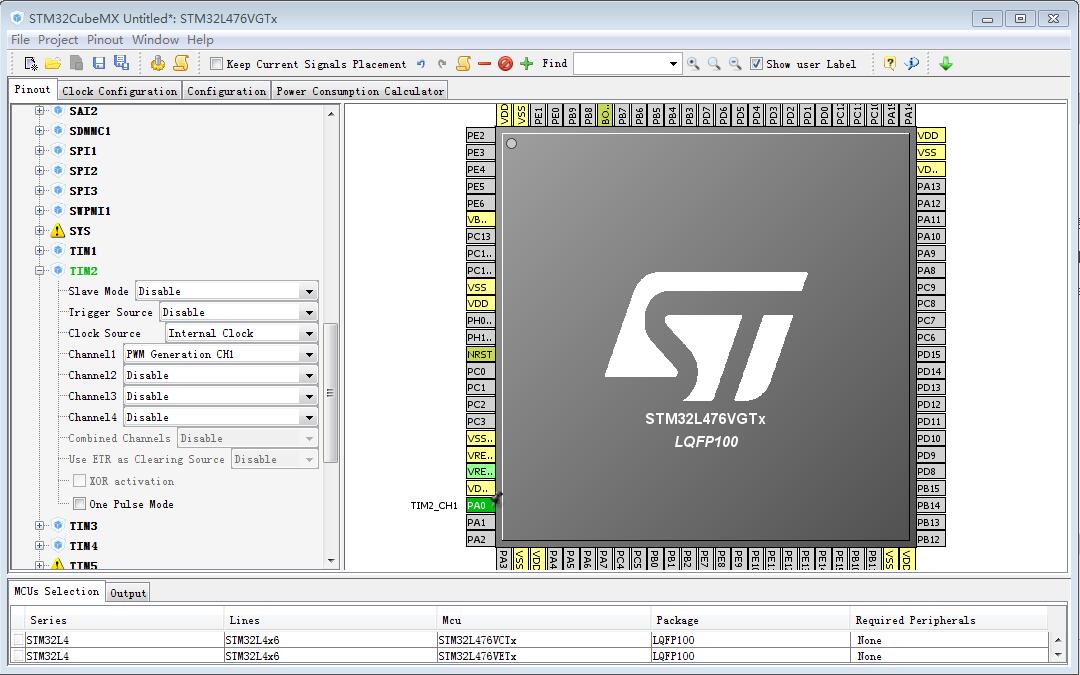
5.1、使用Cube MX---->new project---->选择单片机型号---->选择TIM2的时钟源、通道及模式
 CUBE_GENERATOR.jpg (32.61 KB, 下载次数: 0)
下载附件
2016-3-30 18:07 上传
CUBE_GENERATOR.jpg (32.61 KB, 下载次数: 0)
下载附件
2016-3-30 18:07 上传
关键词:STM32、CubeMX、DMA、TIM、PWM、伺服电机控制
1、关于ST的CubeMX,目前来说,让人又爱又恨,恨比爱多。一是从标准库转用Cube库比较费劲,二是ST不在更新标准库,新出的片子只能用Cube库或直接玩寄存器,三是目前来说Cbue里面到处都是地雷.....
2、项目开始前从网上查了一些精确产生PWM脉冲个数的方法,引述如下:
1)外部再弄个IO口接到PWM脚上,用外部中断的办法,单独来计数。此办法可行,但非常不科学,并且浪费资源。
2)使用定时器,使用一个和PWM频率一致的定时器,使用定时器中断来计数。此方法比第一种办法好了很多,但是仍然感觉比较笨,并且单片机会频繁的进中断......
3)利用定时器内部互联,一个定时器的给另一个定时器提供时钟,主从模式,一个PWM输出脉冲给另一个定时提供时钟,每来一个脉冲,计数器值+1,当+到指定个数后,产生一次中断,然后关闭PWM输出。此方法还是浪费资源,且多路电机控制需 要产生多路频率不同、个数不同的脉冲时就不能满足要求了。
4)使用DMA来控制发送的脉冲数,最大可以65535个,如果想使用不同频率和脉宽,可以设置不同的装载值,如果你发送的脉冲数超过65535个,则可以使用DMA传输完成中断中切换DMA传输的数据起始地址及发送数量,继续发送。这个方法即方便,又减轻CPU的负担,可以同时驱动多个电机工作,还可以根据电机的启动-运行-停止使用不同的频率。
3、上数第4)种方法甚好,只是没有大神们没能具体说明如何实现,根据项目需要,选定第4)种方式实现多路、不同频率、不同脉宽、数量精确可控的PWM波。项目仍在开展中,时间有限,本帖今天起开始说说第4)方式的具体实现方法。
4、硬件平台:STM32L476G-DISCO,TIM2、CH1、PA0、DMA1,软件平台:STM32CubeMX+MDK V5.15。
5、软件实现步骤及关键点说明......回家了,待续......
5.1、使用Cube MX---->new project---->选择单片机型号---->选择TIM2的时钟源、通道及模式
CUBE_GENERATOR.jpg (32.61 KB, 下载次数: 0)
下载附件
2016-3-30 18:07 上传
友情提示: 此问题已得到解决,问题已经关闭,关闭后问题禁止继续编辑,回答。
5.3 需要另外做的工作
初始化后,调用如下两个函数,重点说说如下两个函数。
HAL_TIM_DMABurst_WriteStart(&htim2, TIM_DMABASE_ARR, TIM_DMA_UPDATE,
(uint32_t*)aSRC_Buffer, TIM_DMABURSTLENGTH_3TRANSFERS);
//函数1,用来配置要传送的目标外设寄存器起始地址,这里配置为:TIM_DMABASE_ARR,即从自动重加载寄存器开始写,产生DMA请求的事件配置为:TIM_DMA_UPDATE 即定时器更新事件产生DMA请求,接下来是要传送的源数据起始地址,设置成要发送的数据数组的首地址,然后是DMA连续传输的数据长度,配置为TIM_DMABURSTLENGTH_3TRANSFERS,即连续传输三组寄存器的值,可以理解为一次定时器一次DMA请求,DMA进行三次数据传输,分别写给了TIM_DMABASE_ARR起的三组寄存器。
HAL_TIM_PWM_Start(&htim2, TIM_CHANNEL_1); //使能比较匹配输出通道,使能定时器
看看第一个函数的原型及内部调用函数:
/**
* @brief Configure the DMA Burst to transfer Data from the memory to the TIM peripheral
* @param htim: TIM handle
* @param BurstBaseAddress: TIM Base address from when the DMA will starts the Data write
* This parameters can be on of the following values:
* @arg TIM_DMABASE_CR1
* @arg TIM_DMABASE_CR2
* @arg TIM_DMABASE_SMCR
* @arg TIM_DMABASE_DIER
* @arg TIM_DMABASE_SR
* @arg TIM_DMABASE_EGR
* @arg TIM_DMABASE_CCMR1
* @arg TIM_DMABASE_CCMR2
* @arg TIM_DMABASE_CCER
* @arg TIM_DMABASE_CNT
* @arg TIM_DMABASE_PSC
* @arg TIM_DMABASE_ARR
* @arg TIM_DMABASE_RCR
* @arg TIM_DMABASE_CCR1
* @arg TIM_DMABASE_CCR2
* @arg TIM_DMABASE_CCR3
* @arg TIM_DMABASE_CCR4
* @arg TIM_DMABASE_BDTR
* @arg TIM_DMABASE_DCR
* @param BurstRequestSrc: TIM DMA Request sources
* This parameters can be on of the following values:
* @arg TIM_DMA_UPDATE: TIM update Interrupt source
* @arg TIM_DMA_CC1: TIM Capture Compare 1 DMA source
* @arg TIM_DMA_CC2: TIM Capture Compare 2 DMA source
* @arg TIM_DMA_CC3: TIM Capture Compare 3 DMA source
* @arg TIM_DMA_CC4: TIM Capture Compare 4 DMA source
* @arg TIM_DMA_COM: TIM Commutation DMA source
* @arg TIM_DMA_TRIGGER: TIM Trigger DMA source
* @param BurstBuffer: The Buffer address.
* @param BurstLength: DMA Burst length. This parameter can be one value
* between: TIM_DMABurstLength_1Transfer and TIM_DMABurstLength_18Transfers.
* @retval HAL status
*/
HAL_StatusTypeDef HAL_TIM_DMABurst_WriteStart(TIM_HandleTypeDef *htim, uint32_t BurstBaseAddress, uint32_t BurstRequestSrc,
uint32_t* BurstBuffer, uint32_t BurstLength)//,uint16_t Bursttimes
{
/* Check the parameters */
assert_param(IS_TIM_DMABURST_INSTANCE(htim->Instance));
assert_param(IS_TIM_DMA_BASE(BurstBaseAddress));
assert_param(IS_TIM_DMA_SOURCE(BurstRequestSrc));
assert_param(IS_TIM_DMA_LENGTH(BurstLength));
if((htim->State == HAL_TIM_STATE_BUSY))
{
return HAL_BUSY;
}
else if((htim->State == HAL_TIM_STATE_READY))
{
if((BurstBuffer == 0 ) && (BurstLength > 0))
{
return HAL_ERROR;
}
else
{
htim->State = HAL_TIM_STATE_BUSY;
}
}
switch(BurstRequestSrc)
{
case TIM_DMA_UPDATE:
{
/* Set the DMA Period elapsed callback */
htim->hdma[TIM_DMA_ID_UPDATE]->XferCpltCallback = TIM_DMAPeriodElapsedCplt;
/* Set the DMA error callback */
htim->hdma[TIM_DMA_ID_UPDATE]->XferErrorCallback = TIM_DMAError ;
/* Enable the DMA channel */ //用来设置传输的源地址、目标地址、DMA传送次数及中断
HAL_DMA_Start_IT(htim->hdma[TIM_DMA_ID_UPDATE], (uint32_t)BurstBuffer, (uint32_t)&htim->Instance->DMAR, ((BurstLength) >> 8) + 1);//Bursttimes
}
break;
case TIM_DMA_CC1:
{
/* Set the DMA Period elapsed callback */
htim->hdma[TIM_DMA_ID_CC1]->XferCpltCallback = TIM_DMADelayPulseCplt;
/* Set the DMA error callback */
htim->hdma[TIM_DMA_ID_CC1]->XferErrorCallback = TIM_DMAError ;
/* Enable the DMA channel */
HAL_DMA_Start_IT(htim->hdma[TIM_DMA_ID_CC1], (uint32_t)BurstBuffer, (uint32_t)&htim->Instance->DMAR, ((BurstLength) >> 8) + 1);
}
break;
case TIM_DMA_CC2:
{
/* Set the DMA Period elapsed callback */
htim->hdma[TIM_DMA_ID_CC2]->XferCpltCallback = TIM_DMADelayPulseCplt;
/* Set the DMA error callback */
htim->hdma[TIM_DMA_ID_CC2]->XferErrorCallback = TIM_DMAError ;
/* Enable the DMA channel */
HAL_DMA_Start_IT(htim->hdma[TIM_DMA_ID_CC2], (uint32_t)BurstBuffer, (uint32_t)&htim->Instance->DMAR, ((BurstLength) >> 8) + 1);
}
break;
case TIM_DMA_CC3:
{
/* Set the DMA Period elapsed callback */
htim->hdma[TIM_DMA_ID_CC3]->XferCpltCallback = TIM_DMADelayPulseCplt;
/* Set the DMA error callback */
htim->hdma[TIM_DMA_ID_CC3]->XferErrorCallback = TIM_DMAError ;
/* Enable the DMA channel */
HAL_DMA_Start_IT(htim->hdma[TIM_DMA_ID_CC3], (uint32_t)BurstBuffer, (uint32_t)&htim->Instance->DMAR, ((BurstLength) >> 8) + 1);
}
break;
case TIM_DMA_CC4:
{
/* Set the DMA Period elapsed callback */
htim->hdma[TIM_DMA_ID_CC4]->XferCpltCallback = TIM_DMADelayPulseCplt;
/* Set the DMA error callback */
htim->hdma[TIM_DMA_ID_CC4]->XferErrorCallback = TIM_DMAError ;
/* Enable the DMA channel */
HAL_DMA_Start_IT(htim->hdma[TIM_DMA_ID_CC4], (uint32_t)BurstBuffer, (uint32_t)&htim->Instance->DMAR, ((BurstLength) >> 8) + 1);
}
break;
case TIM_DMA_COM:
{
/* Set the DMA Period elapsed callback */
htim->hdma[TIM_DMA_ID_COMMUTATION]->XferCpltCallback = TIMEx_DMACommutationCplt;
/* Set the DMA error callback */
htim->hdma[TIM_DMA_ID_COMMUTATION]->XferErrorCallback = TIM_DMAError ;
/* Enable the DMA channel */
HAL_DMA_Start_IT(htim->hdma[TIM_DMA_ID_COMMUTATION], (uint32_t)BurstBuffer, (uint32_t)&htim->Instance->DMAR, ((BurstLength) >> 8) + 1);
}
break;
case TIM_DMA_TRIGGER:
{
/* Set the DMA Period elapsed callback */
htim->hdma[TIM_DMA_ID_TRIGGER]->XferCpltCallback = TIM_DMATriggerCplt;
/* Set the DMA error callback */
htim->hdma[TIM_DMA_ID_TRIGGER]->XferErrorCallback = TIM_DMAError ;
/* Enable the DMA channel */
HAL_DMA_Start_IT(htim->hdma[TIM_DMA_ID_TRIGGER], (uint32_t)BurstBuffer, (uint32_t)&htim->Instance->DMAR, ((BurstLength) >> 8) + 1);
}
break;
default:
break;
}
/* configure the DMA Burst Mode */
htim->Instance->DCR = BurstBaseAddress | BurstLength;//这里设置的是DBL和DBA
/* Enable the TIM DMA Request */
__HAL_TIM_ENABLE_DMA(htim, BurstRequestSrc);
htim->State = HAL_TIM_STATE_READY;
/* Return function status */
return HAL_OK;
}
此函数中,只有第一个case语句及函数最后几句对我们有用。先看一个case语句中的调用函数
/**
* @brief Start the DMA Transfer with interrupt enabled.
* @param hdma: pointer to a DMA_HandleTypeDef structure that contains
* the configuration information for the specified DMA Channel.
* @param SrcAddress: The source memory Buffer address
* @param DstAddress: The destination memory Buffer address
* @param DataLength: The length of data to be transferred from source to destination
* @retval HAL status
*/
HAL_StatusTypeDef HAL_DMA_Start_IT(DMA_HandleTypeDef *hdma, uint32_t SrcAddress, uint32_t DstAddress, uint32_t DataLength)
{
/* Process locked */
__HAL_LOCK(hdma);
/* Change DMA peripheral state */
hdma->State = HAL_DMA_STATE_BUSY;
/* Check the parameters */
assert_param(IS_DMA_BUFFER_SIZE(DataLength));
/* Disable the peripheral */
__HAL_DMA_DISABLE(hdma);
/* Configure the source, destination address and the data length */
DMA_SetConfig(hdma, SrcAddress, DstAddress, DataLength);//设置源地址、目标地址、DMA传输次数
/* Enable the transfer complete interrupt */
/* Enable the Half transfer complete interrupt */
/* Enable the transfer Error interrupt */
__HAL_DMA_ENABLE_IT(hdma, DMA_IT_TC);// | DMA_IT_HT | DMA_IT_TE 只开DMA传输完成中断,不开半传输中断及错误中断
/* Enable the Peripheral */
__HAL_DMA_ENABLE(hdma);
return HAL_OK;
}
其中函数:
/* Configure the source, destination address and the data length */
DMA_SetConfig(hdma, SrcAddress, DstAddress, DataLength);//设置源地址、目标地址、DMA传输次数,这里有两个比较难以理解的寄存器,TIMx_DMAR和TIMx_DCR,不要去看TIM2的寄存器,去看TIM1的对应寄存器,应为后者讲的更详细些,数据手册如下:
5.jpg (52.23 KB, 下载次数: 0)
下载附件
2016-4-1 16:53 上传
有成果了吧..........
本着求真、务实、讲科学的态度,还要进行验证测试
一周热门 更多>