这几天在弄个1602液晶显示时钟,用DS1302时钟芯片提供时间;但在中途出现了点小问题,
对着DS1302时序图写完这部分程序,想试试程序是否对,就用一个8个LED灯P0接收DS1302的数据,
如果8个LED灯发生变化说明没有对着时序图写的这部分驱动没问题,但发现并不这么理想,8个LED全亮(LED共阳),
没有发生变化,说明DS1302驱动程序那部分有问题;可调试了很久也不知道哪里出错了.望好心人大神们帮助下。
(很想知道哪里错了,有尝的求救,如果有意愿帮助指导下的,可以加我QQ1097957773,,谢谢)
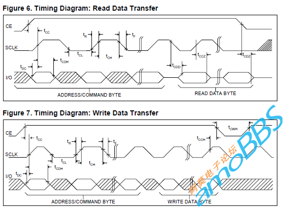
以下是时序图:
 QQ截图未命名.png (45.26 KB, 下载次数: 0)
下载附件
DS1302时序图
2012-9-8 13:07 上传
以下是DS1302驱动部分程序:
#include <reg52.h>
#include <intrins.h>
#define uint unsigned int
#define uchar unsigned char
void DS1302_COMMAND_WRITE(uchar adr);
void DS1302_DATA_WRITE(uchar date);
void switch_10_16(uchar transition);
void delay(uint z);
void delaynop();
uchar receive_io,shift_date;
void delaynop()
{
_nop_();
_nop_();
_nop_();
_nop_();
}
/***************************/
/* */
/* DS1302时钟位定义 */
/* */
/***************************/
sbit RST=P2^0;
sbit io=P2^2;
sbit SCLK=P2^1;
/***************************************/
/* */
/* 延时函数 */
/* */
/***************************************/
void delay(uint z)
{
uint x,y;
for(x=z;x>0;x--)
for(y=110;y>0;y--);
}
/***************************************/
/* */
/* DS1302时钟写保护函数 */
/* */
/***************************************/
void WRITE_PROTECT(uchar protect)
{
DS1302_COMMAND_WRITE(0x8E);//DS1302 CONTROL地址位
DS1302_DATA_WRITE(protect);//DS1302 CONTROL数据位
}
/*****************************************/
/* */
/* DS1302时钟地址写操作函数 */
/* */
/*****************************************/
void DS1302_COMMAND_WRITE(uchar adr)
{
uchar i;
RST=0;
SCLK=0;
RST=1; //高电平开始
delaynop();
for(i=0;i<8;i++)
{
adr=adr>>1;
io=adr&0x80;//1位送入DS1302芯片中
SCLK=1;//高脉冲送出数据
delaynop();
SCLK=0;
delaynop();
}
} //地址写完 SCLK为低电平
/***************************************/
/* */
/* DS1302时钟数据写操作函数 */
/* */
/***************************************/
void DS1302_DATA_WRITE(uchar date)
{
uchar i;
switch_10_16(date); //数值转换
for(i=0;i<8;i++)
{
io=shift_date&0x01; //低位与运算判断0和1
shift_date=shift_date>>1;//转换后的数据进行移位传输
SCLK=1;//高脉冲送出数据
delaynop();
SCLK=0;
delaynop();
}
SCLK=1;//写完后按时序图SCLK先置高
RST=0;//RST在置低
}
/***************************************/
/* */
/* DS1302时钟数据读操作函数 */
/* */
/***************************************/
void DS1302_READ(uchar adre)
{
uchar i;
receive_io=0;
DS1302_COMMAND_WRITE(adre);//写完地址后SCLK为低电平,需要一个高电平过度在开始读操作
SCLK=1;
delaynop();
for(i=0;i<8;i++)
{
SCLK=0;//低脉冲读走数据
delaynop();
receive_io=receive_io>>1;
if(io==1)
{
receive_io=receive_io|0x80; //高位补1
}
else
{
receive_io=receive_io|0x00; //高位补0
}
}
SCLK=1;
delaynop();
RST=0;
}
/*****************************************/
/* */
/* DS1302时钟总体写操作函数 */
/* */
/*****************************************/
void DS1302_WRITE(uchar adress,uchar dat)
{
DS1302_COMMAND_WRITE(adress);
DS1302_DATA_WRITE(dat);
}
/***************************************/
/* */
/* 发送_数值转换函数 */
/* */
/***************************************/
void switch_10_16(uchar transition)
{
uchar ge,shi;
shi=transition/10;
ge=transition%10;
shift_date=shi*16+ge;
}
void main()
{
WRITE_PROTECT(0x00); //去除写保护
delaynop();
DS1302_WRITE(0x80,13);
delaynop();
while(1)
{
DS1302_READ(0x81);
delaynop();
P0=receive_io;
}
}
对着DS1302时序图写完这部分程序,想试试程序是否对,就用一个8个LED灯P0接收DS1302的数据,
如果8个LED灯发生变化说明没有对着时序图写的这部分驱动没问题,但发现并不这么理想,8个LED全亮(LED共阳),
没有发生变化,说明DS1302驱动程序那部分有问题;可调试了很久也不知道哪里出错了.望好心人大神们帮助下。
(很想知道哪里错了,有尝的求救,如果有意愿帮助指导下的,可以加我QQ1097957773,,谢谢)
以下是时序图:
 QQ截图未命名.png (45.26 KB, 下载次数: 0)
下载附件
DS1302时序图
2012-9-8 13:07 上传
以下是DS1302驱动部分程序:
#include <reg52.h>
#include <intrins.h>
#define uint unsigned int
#define uchar unsigned char
void DS1302_COMMAND_WRITE(uchar adr);
void DS1302_DATA_WRITE(uchar date);
void switch_10_16(uchar transition);
void delay(uint z);
void delaynop();
uchar receive_io,shift_date;
void delaynop()
{
_nop_();
_nop_();
_nop_();
_nop_();
}
/***************************/
/* */
/* DS1302时钟位定义 */
/* */
/***************************/
sbit RST=P2^0;
sbit io=P2^2;
sbit SCLK=P2^1;
/***************************************/
/* */
/* 延时函数 */
/* */
/***************************************/
void delay(uint z)
{
uint x,y;
for(x=z;x>0;x--)
for(y=110;y>0;y--);
}
/***************************************/
/* */
/* DS1302时钟写保护函数 */
/* */
/***************************************/
void WRITE_PROTECT(uchar protect)
{
DS1302_COMMAND_WRITE(0x8E);//DS1302 CONTROL地址位
DS1302_DATA_WRITE(protect);//DS1302 CONTROL数据位
}
/*****************************************/
/* */
/* DS1302时钟地址写操作函数 */
/* */
/*****************************************/
void DS1302_COMMAND_WRITE(uchar adr)
{
uchar i;
RST=0;
SCLK=0;
RST=1; //高电平开始
delaynop();
for(i=0;i<8;i++)
{
adr=adr>>1;
io=adr&0x80;//1位送入DS1302芯片中
SCLK=1;//高脉冲送出数据
delaynop();
SCLK=0;
delaynop();
}
} //地址写完 SCLK为低电平
/***************************************/
/* */
/* DS1302时钟数据写操作函数 */
/* */
/***************************************/
void DS1302_DATA_WRITE(uchar date)
{
uchar i;
switch_10_16(date); //数值转换
for(i=0;i<8;i++)
{
io=shift_date&0x01; //低位与运算判断0和1
shift_date=shift_date>>1;//转换后的数据进行移位传输
SCLK=1;//高脉冲送出数据
delaynop();
SCLK=0;
delaynop();
}
SCLK=1;//写完后按时序图SCLK先置高
RST=0;//RST在置低
}
/***************************************/
/* */
/* DS1302时钟数据读操作函数 */
/* */
/***************************************/
void DS1302_READ(uchar adre)
{
uchar i;
receive_io=0;
DS1302_COMMAND_WRITE(adre);//写完地址后SCLK为低电平,需要一个高电平过度在开始读操作
SCLK=1;
delaynop();
for(i=0;i<8;i++)
{
SCLK=0;//低脉冲读走数据
delaynop();
receive_io=receive_io>>1;
if(io==1)
{
receive_io=receive_io|0x80; //高位补1
}
else
{
receive_io=receive_io|0x00; //高位补0
}
}
SCLK=1;
delaynop();
RST=0;
}
/*****************************************/
/* */
/* DS1302时钟总体写操作函数 */
/* */
/*****************************************/
void DS1302_WRITE(uchar adress,uchar dat)
{
DS1302_COMMAND_WRITE(adress);
DS1302_DATA_WRITE(dat);
}
/***************************************/
/* */
/* 发送_数值转换函数 */
/* */
/***************************************/
void switch_10_16(uchar transition)
{
uchar ge,shi;
shi=transition/10;
ge=transition%10;
shift_date=shi*16+ge;
}
void main()
{
WRITE_PROTECT(0x00); //去除写保护
delaynop();
DS1302_WRITE(0x80,13);
delaynop();
while(1)
{
DS1302_READ(0x81);
delaynop();
P0=receive_io;
}
}
友情提示: 此问题已得到解决,问题已经关闭,关闭后问题禁止继续编辑,回答。
ds1302 bad.PNG (26.63 KB, 下载次数: 0)
下载附件
2012-9-9 00:23 上传
the rtc was reset to 13 (0x13 in bcd format) initially.
so from 1s - 2s, the second should be 13 (0x14 in bcd format). that corresponds to P3.4 = 1, P3.2 = 1, and P3.x cleared -> P3 = 0x14, as you can see on the chart.
from 6 - 7s, the second should be 19 (0x19 in bcd format). P3 reads 0x19, correctly.
from 7s - 8s, the second will advance to 20, which causes the bcd reading to go from 0x19 to 0x20. You can see that there.
If the code I posted doesn't work on your hardware, you have other problems.
一周热门 更多>