看到
想做一个孵小鸡的装置,让孩子孵一只小鸡出来,应该用什么样的加热器件,请指教。
里面提到了二极管的温度测量
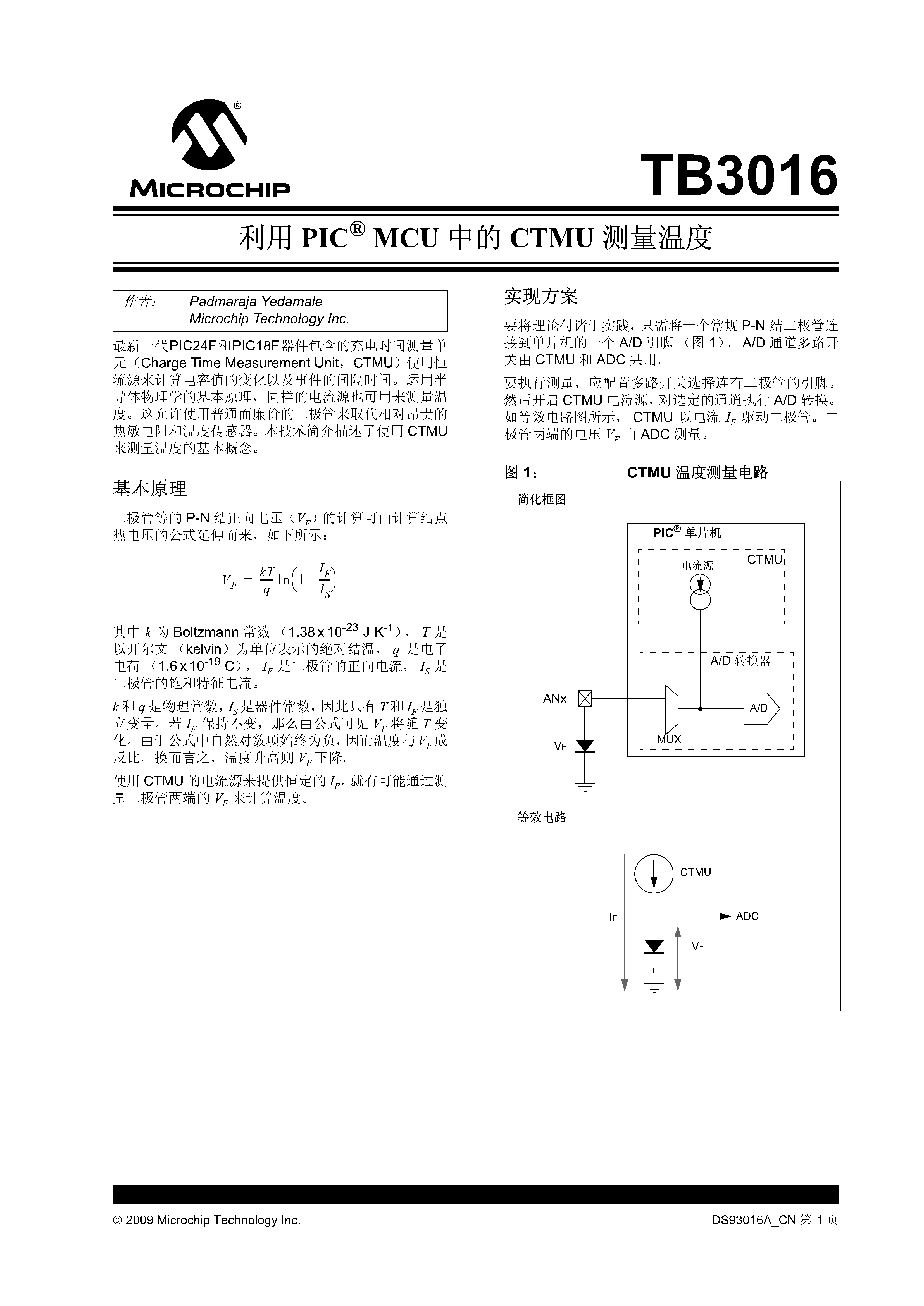
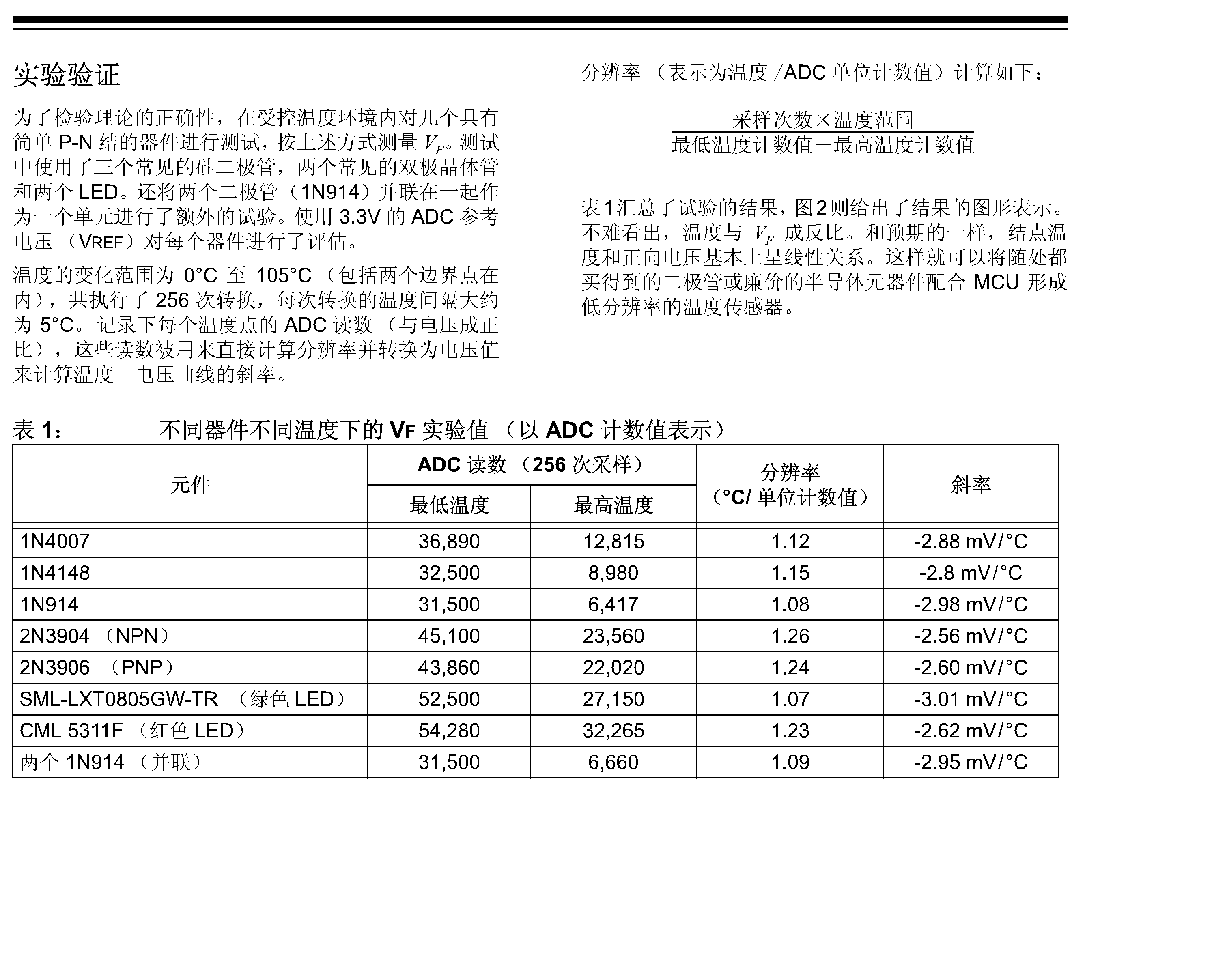
上网找了一下原理.张贴如下

(原文件名:D__资料_电子_利用PIC_MCU中的CTMU _二极管_1N4148测量温度.png)

(原文件名:D__资料_电子_利用PIC_MCU中的CTMU _二极管_1N4148测量温度_00002.png)

(原文件名:D__资料_电子_利用PIC_MCU中的CTMU _二极管_1N4148测量温度_00003.png)

(原文件名:D__资料_电子_利用PIC_MCU中的CTMU _二极管_1N4148测量温度_00005.png)

(原文件名:D__资料_电子_利用PIC_MCU中的CTMU _二极管_1N4148测量温度_00006.png)
点击此处下载 ourdev_545583.PDF(文件大小:342K) (原文件名:利用PIC_MCU中的CTMU _二极管_1N4148测量温度.PDF)
点击此处下载 ourdev_545584.PDF(文件大小:337K) (原文件名:充电时间测量单元CTMU.PDF)
想做一个孵小鸡的装置,让孩子孵一只小鸡出来,应该用什么样的加热器件,请指教。
里面提到了二极管的温度测量
上网找了一下原理.张贴如下

(原文件名:D__资料_电子_利用PIC_MCU中的CTMU _二极管_1N4148测量温度.png)

(原文件名:D__资料_电子_利用PIC_MCU中的CTMU _二极管_1N4148测量温度_00002.png)

(原文件名:D__资料_电子_利用PIC_MCU中的CTMU _二极管_1N4148测量温度_00003.png)

(原文件名:D__资料_电子_利用PIC_MCU中的CTMU _二极管_1N4148测量温度_00005.png)

(原文件名:D__资料_电子_利用PIC_MCU中的CTMU _二极管_1N4148测量温度_00006.png)
点击此处下载 ourdev_545583.PDF(文件大小:342K) (原文件名:利用PIC_MCU中的CTMU _二极管_1N4148测量温度.PDF)
点击此处下载 ourdev_545584.PDF(文件大小:337K) (原文件名:充电时间测量单元CTMU.PDF)
友情提示: 此问题已得到解决,问题已经关闭,关闭后问题禁止继续编辑,回答。
======code==========
#include <htc.h>
#include <string.h>
#include "delay.h"
//#include "lcd_4bit.h"
#include "lcd_3wi.h"
__CONFIG(MCLRDIS & BORDIS & WDTDIS & PWRTEN & INTIO);
#define sleep() asm("sleep") //put the mcu to sleep
#define AN0 (1<<0) //an0
#define AN2 (1<<2) //an2 - an1 used a vref in this application
#define ADC_CH0 AN0 //adc on an0
#define ADC_CH1 AN2 //adc on an2
#define LCD_Line_ADCX LCD_Line0 //L ch on lcd_line0
#define LCD_Line_Temp LCD_Line1 //R ch on lcd_line1
#define LED_PIN (1<<5) //led on GPIO1
#define PA_SET(bits) PORTA |= (bits); //set bits on porta
#define PA_CLR(bits) PORTA &=~(bits); //clear bits on porta
#define PA_FLP(bits) PORTA ^= (bits); //flip bits on porta
#define DLY_main_loop 300 //main loop delay, in ms
#define Vref 2000000ul //reference voltage, in uv. Vref=2v
#define adc2_uv(adc_int) ((signed long) (Vref*((unsigned long)adc_int))>>10) //convert 10 bits to uv. so 1000 = 1mv.
//caliberation temperatures
#define T1 0l //1st caliberation temperature, in 0.01C
#define adc_uv_at_T1 699218l //adc reading, in uv, at T1
#define T2 10000l //2nd caliberation temperature, in 0.01C
#define adc_uv_at_T2 750000l //adc reading, in uv, at T2
#define uv2_tempC(uv) T1+(signed long) (T2-T1)*((uv)-adc_uv_at_T1)/(adc_uv_at_T2-adc_uv_at_T1) //convert uv to C. 2 decimal points
#define Tacq_delay() NOP(); NOP(); NOP(); NOP(); NOP(); NOP() //delay for tacq
const unsigned char str_adcx[] ="ADC : ";
const unsigned char str_volt[] ="Volt: mv";
const unsigned char str_tempC[]="Temp: C";
const unsigned char str_0[]="16F684 TempMeter";
const unsigned char str_v[]="version 0.2-1234";
unsigned char vRAM[17];
unsigned long random_vN(void) { //using von Neumann middle square approach to return a random number
static unsigned long seed=5634; //3021, 3421
seed=((seed*seed) & 0x00ffff00) >> 8;
return seed;
}
void adc_init(void) { //initialize the adc
// ADCON0 = config_mask;
ADCS2=0, ADCS1=1, ADCS0=0; //adc running at fosc/32
ADFM=1; //adc results right justified
VCFG=1; //Vref on porta2/an2
ADON=0; //adc off
}
unsigned int adc_read(unsigned char ch){//read adc
ADON=1; //turn on the adc
// ANSEL |= ch; //select the adc channel, and adc at fosc/32
// TRISIO |= ch; //turn it as input
// CHS1=(ch-1) >> 1; //select the channel
// CHS0=(ch-1);
switch (ch) {
case AN0: CHS2=0, CHS1=0, CHS0=0, ANSEL=AN0; break;
case AN2: CHS2=0, CHS1=1, CHS0=0, ANSEL=AN2; break;
default: NOP(); NOP(); NOP(); NOP(); NOP(); break;
}
// delay_us(1); //turn on the adc
// may need some delays here
Tacq_delay(); //delay for tacq
GODONE=1; //start the adc
while (GODONE) continue; //wait for the adc to complete;
ADON=0; //turn off the adc
return (ADRESH<<8) + ADRESL;
// return random_vN() & 0x3ff; //return a random 10bit number, for testing purposes
}
void ltoa(char *s, signed long ul, unsigned char length, unsigned char dp) { //convert unsigned long to a string, 3 dps
unsigned char i;
char sign=0; //no sign
if (ul<0) {
ul=-ul;
sign=-1; //negative sign
} else sign=+1; //positive sign
i=length;
do {
if (i==(length-dp)) s[i--]='.';
s[i--]=ul % 10 + '0';
ul = ul / 10;
} while (ul);
switch (sign) {
case -1: s='-'; break;
case +1: s='+'; break;
}
}
void mcu_init(void) {
CMCON0=0x07; //turn off comparators;
//TRISIO=0b11; //input on GPIO0, all others digital output;
ANSEL=0x00; //all ports gpio
IRCF2=1, IRCF1=1, IRCF0=0; //4Mhz
}
void main(void)
{
//unsigned char temp=0, gSPad[9], i;
unsigned int i, tmp, tmp2;
//unsigned int val_L, val_R;
mcu_init(); //initialize the mcu
lcd_init(); //initialize the lcd
adc_init(); //initialize the adc
strcpy(vRAM, str_0); lcd_display(LCD_Line0, vRAM);
strcpy(vRAM, str_v); lcd_display(LCD_Line1, vRAM); delay_ms(50);
strcpy(vRAM, str_adcx); lcd_display(LCD_Line_ADCX, vRAM);
strcpy(vRAM, str_tempC); lcd_display(LCD_Line_Temp, vRAM);
// sleep();
while (1){
//TODO Auto-generated main function
i=adc_read(ADC_CH0);
// strcpy(vRAM, str_adcx); ltoa(&vRAM[5], i, 7); lcd_display(LCD_Line_ADCX, vRAM);
// the following is for calibration purposes
strcpy(vRAM, str_volt); ltoa(&vRAM[5], adc2_uv(i)/100, 8,1); lcd_display(LCD_Line_ADCX, vRAM);
// the following is for actual displaying, in 1/100th of C. so 4568C means 45.68C; -423C means -4.23C
strcpy(vRAM, str_tempC); ltoa(&vRAM[5], uv2_tempC(adc2_uv(i)), 8,2); lcd_display(LCD_Line_Temp, vRAM);
delay_ms(DLY_main_loop); //delay some time
}
}
==========================
here is the display.
(原文件名:16F684 temp diode v2.PNG)
一周热门 更多>