{var%20f='http://v.t.sina.com.cn/share/share.php?appkey=1515056452',u=z||d.location,p=['&url=',e(u),'&title=',e(t||d.title),'&source=',e(r),'&sourceUrl=',e(l),'&content=',c||'gb2312','&pic=',e(p||'')].join('');function%20a(){if(!window.open([f,p].join(''),'mb',['toolbar=0,status=0,resizable=1,width=440,height=430,left=',(s.width-440)/2,',top=',(s.height-430)/2].join('')))u.href=[f,p].join('');};if(/Firefox/.test(navigator.userAgent))setTimeout(a,0);else%20a();})(screen,document,encodeURIComponent,'','','https://www.xiaopingtou.cn//data/attach/topic/topicKPo7gB.jpg', '推荐 小笨蛋 的文章《MSM8909平台UIM驱动流程》','https://www.xiaopingtou.net/article-52573.html','页面编码gb2312|utf-8默认gb2312'));)
UIM卡上电需要满足下面的时序。


UIM上电时序 UIM下电时序
MSM8909平台UIM初始化流程如下。

在initialize_intctrl中设置了UART接收数据的中断服务程序为uimIntctrlIsr,当UART的DATA数据线为接收模式时,一旦DATA线上面有数据,uimIntctrlIsr函数就会被调用。

进入uim_reset_uim函数分析
#define UIM_GET_CMD_MODE(command) ((command >> 8) & 0x0F)
uim_ptr->command.cmd_ptr->hdr.command在前面被赋值为0x0100,这样uim_ptr->state.cmd_mode的值就是0x01,在switch中会走UIM_GENERIC_CMD分支。UIM_GENERIC_CMD是一个宏,在modem_procuimuimdrvsrcuimi.h中定义:
uim_generic_command调用完uim_power_up后,通过rex_set_sigs发送UIM_CMD_RSP_SIG信号。返回到uim_task_common函数,在调用完uim_start_initial_powerup后,uim_task_common会进入for循环。
进入uim_generic_command_response函数分析。
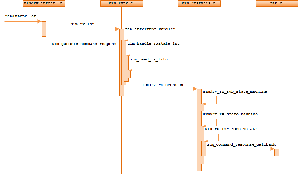
uim_read_rx_fifo会读取DATA线上的数据,保存早uim_ptr->card_cmd.uart_rx_buf中。
UIM上电时序 UIM下电时序
MSM8909平台UIM初始化流程如下。
在initialize_intctrl中设置了UART接收数据的中断服务程序为uimIntctrlIsr,当UART的DATA数据线为接收模式时,一旦DATA线上面有数据,uimIntctrlIsr函数就会被调用。
/* Initialize interrupt controller */
void initialize_intctrl(uim_instance_global_type *uim_ptr)
{
  . . . . . .
  DalInterruptController_RegisterISR(uim_hw_if.intctrl[uim_instance].m_IntCtrl_handle_ptr,
                                     uim_hw_if.intctrl[uim_instance].m_uartIRQNum,
                                     (DALISR) uimIntctrlIsr,// 设置UART接收中断服务函数
                                     (const DALIRQCtx) uim_ptr,
                                     DALINTRCTRL_ENABLE_LEVEL_HIGH_TRIGGER);
. . . . . .
} /* initialize_intctrl */ 在uim_initialize_state中,设置UIM的当前工作电压为1.8V,UIM支持的最大电压为3V。void uim_initialize_state
(
uim_instance_global_type *uim_ptr
)
{
/* - - - - - - - - - - - - - - - - - - - - - - - - - - - - - - - - - - - - */
/* Initialize the uim Rx character ISR processing state. */
uim_ptr->rxtx_state_machine.rx_state = UIM_RX_PROCESS_IDLE;
if (uim_ptr->hardware.uim_ldo.customize_ldo_setting &&
uim_ptr->hardware.uim_ldo.desired_voltage_class != UIM_VOLTAGE_CLASS_INVALID)
{
/* Set the UIM interface voltage to desired voltage class */
uim_ptr->state.current_voltage_class = uim_ptr->hardware.uim_ldo.desired_voltage_class;
uim_ptr->state.max_possible_voltage_class = uim_ptr->hardware.uim_ldo.desired_voltage_class;
}
else
{
/* Set the UIM interface voltage to the minimum voltage class */
// 设置UIM的当前电源电压为1.8V
uim_ptr->state.current_voltage_class = UIM_VOLTAGE_CLASS_C;
// 设置UIM支持的最大电压为3V
uim_ptr->state.max_possible_voltage_class = UIM_VOLTAGE_CLASS_B;
}
} /* uim_initialize_state */UIM_VOLTAGE_CLASS_C和UIM_VOLTAGE_CLASS_B在modem_procuimuimdrvsrcuimdrv.h中定义。/* The enum type describes the voltage classes supported on the UIM interface.
The list must start at the lowest voltage and progress top the highest voltage
in order. */
typedef enum {
UIM_VOLTAGE_CLASS_INVALID,
UIM_VOLTAGE_CLASS_C, /* Use 1.8 volts */
UIM_VOLTAGE_CLASS_B, /* Use 3 volts */
} uim_voltage_class_type;SET_UIM_BAUD_RATE_SLOT函数用来设置UART通信的波特率,该函数在modem_procuimuimdrvsrchwclkregimeuimdrv_clk.c中定义。void SET_UIM_BAUD_RATE_SLOT
(
uim_instance_enum_type uim_instance,
uim_clock_rate_conversion_factor_type nFI,
uim_baud_rate_adjustment_factor_type nDI
)
{
uim_instance_global_type *uim_ptr = uim_get_instance_ptr(uim_instance);
if(uim_ptr == NULL)
{
UIM_MSG_ERR_0("SET_UIM_BAUD_RATE_SLOT: uim_ptr is NULL");
return;
}
/* Store the current FI and DI */
// 设置FI参数
uim_ptr->state.FI_current = nFI;
// 设置DI参数
uim_ptr->state.DI_current = nDI;
setBaudRate(uim_ptr->id, nFI, nDI);
return;
} /* SET_UIM_BAUD_RATE_SLOT */UART波特率的计算方法:CLK / (FI / DI),CLK一般输出为3.84MHZ或者4.8MHZ,本例中SET_UIM_BAUD_RATE_SLOT传入的参数分别是UIM_CRCF_372_1和UIM_BRAF_1。/* Set the UART clock to the default values. */
SET_UIM_BAUD_RATE_SLOT ( uim_ptr->id, UIM_CRCF_372_1, UIM_BRAF_1);UART的波特率等于3840000 / (372 / 1) = 10323。这个是大部分UIM卡的速率,叫做一倍速卡,还有一种4倍速的卡,波特率等于3840000 / (372 / 4) = 41290,高通平台目前支持一倍速的卡。uim_dev_init中设置的波特率在后面给UIM卡复位的时候会再次被更改,后面会提到。UIM上电流程如下。进入uim_reset_uim函数分析
void uim_reset_uim
(
rex_sigs_type *mask,
boolean me_powerup,
uim_instance_global_type *uim_ptr
)
{
. . . . . .
/* Indicate that we did not receive the ATR */
uim_ptr->atr.atr_received = FALSE;
/* reset the voltage_class_known_from_atr varialbe */
uim_ptr->flag.voltage_class_known_from_atr = FALSE;
if (me_powerup)
{
. . . . . .
/* command to power up the UIM due to task start up */
if (uim_ptr->command.static_cmd_buf.hdr.command == UIM_HOTSWAP_CARD_INS_F)
{
UIMDRV_MSG_LOW_1(uim_ptr->id,"HOTSWAP: uim_reset_uim due to card inserted command for slot 0x%x",
uim_ptr->command.static_cmd_buf.hdr.slot);
}
uim_ptr->command.static_cmd_buf.hdr.command = UIM_INTERNAL_ME_PUP_F;
}
else
{
. . . . . .
}
uim_process_command(mask, uim_ptr);
} /* uim_reset_uim() */uim_ptr->command.static_cmd_buf.hdr.command = UIM_INTERNAL_ME_PUP_F;设置状态机的初始状态。UIM_INTERNAL_ME_PUP_F是一个宏,值为0x0100,在modem_procuimapiuim_v.h中定义:/* Command types */
typedef enum {
UIM_NO_SUCH_COMMAND_F = 0, /* No such command */
UIM_INTERNAL_ME_PUP_F = 0x0100,/* POWER UP UIM due to task start up */
UIM_INTERNAL_WAKE_UP_F, /* Power up due to Power management */
. . . . . .
UIM_MAX_F
} uim_cmd_name_type;接下来调用uim_process_command函数:void uim_process_command
(
/* Pointer to received command */
rex_sigs_type *mask,
/* rex signals type mask */
uim_instance_global_type *uim_ptr
)
{
. . . . . .
/* If the current directory is current to process the command, then
process the command */
if(FALSE == intermediate_select.is_needed)
{
. . . . . .
/* Get the mode of the command */
uim_ptr->state.cmd_mode =
(uim_command_mode_type) UIM_GET_CMD_MODE((int)uim_ptr->command.cmd_ptr->hdr.command);
switch (uim_ptr->state.cmd_mode)
{
. . . . . .
case UIM_GENERIC_CMD:
default:
command_transacted = uim_process_generic_command (uim_ptr);
break;
} /* end for switch */
}
else
{
. . . . . .
}
. . . . . .
} /* uim_process_command */UIM_GET_CMD_MODE是一个宏,在modem_procuimuimdrvsrcuim.c中定义:#define UIM_GET_CMD_MODE(command) ((command >> 8) & 0x0F)
uim_ptr->command.cmd_ptr->hdr.command在前面被赋值为0x0100,这样uim_ptr->state.cmd_mode的值就是0x01,在switch中会走UIM_GENERIC_CMD分支。UIM_GENERIC_CMD是一个宏,在modem_procuimuimdrvsrcuimi.h中定义:
typedef enum {
UIM_NO_SUCH_CMD = 0x0,
UIM_GENERIC_CMD = 0x1,
UIM_GSM_CMD = 0x2,
UIM_CDMA_CMD = 0x3,
UIM_USIM_CMD = 0x4,
UIM_ISIM_CMD = 0x5
} uim_command_mode_type;接下来进入uim_process_generic_command函数:boolean uim_process_generic_command
(
uim_instance_global_type *uim_ptr
)
{
. . . . . .
/* Process the generic command. */
switch (uim_ptr->command.cmd_ptr->hdr.command)
{
case UIM_INTERNAL_ME_PUP_F: /* POWER UP UIM due to task start up */
uim_ptr->command.generic_state_ptr = UIM_INTERNAL_PUP_STATES;
break;
. . . . . .
}
if (status)
{
/* Call the state machine. */
uim_generic_command (uim_ptr);
}
else
{
. . . . . .
}
return(status);
} /* uim_process_generic_command() */uim_ptr->command.cmd_ptr->hdr.command在前面被赋值为UIM_INTERNAL_ME_PUP_F,所以在switch中会走UIM_INTERNAL_ME_PUP_F分支。在这个case分支中,执行了让uim_ptr->command.generic_state_ptr 指针指向了UIM_INTERNAL_PUP_STATES数组,该数组在modem_procuimuimdrvsrcuimgen.c中定义:/* State configuration for the commands. */
/* UIM_INTERNAL_ME_PUP_F = 0x0100, POWER UP UIM due to task start up */
static const uim_generic_state_type UIM_INTERNAL_PUP_STATES[] =
{ UIM_POWER_UP_ST, UIM_RESET_ST,
UIM_DELAY_AFTER_ATR_ST, UIM_PPS_ST, UIM_UPDATE_OP_PARAMS_ST,
#if defined( FEATURE_UIM_T_1_SUPPORT )
UIM_IFS_NEG_ST,
#endif /* FEATURE_UIM_T_1_SUPPORT */
UIM_SEND_STATUS_ST,
UIM_CHECK_CHARACTERISTICS_ST,
UIM_TERMINAL_CAPABILITY_ST,
UIM_SELECT_ICCID_ST, UIM_READ_ICCID_ST,
UIM_CHECK_FOR_CDMA_DF,
UIM_DONE_ST };后面会通过对generic_state_ptr指针的操作来进行状态机的切换。接下来调用uim_generic_command函数。void uim_generic_command
(
uim_instance_global_type *uim_ptr
)
{
. . . . . .
/* Build an APDU based on the UIM generic state */
switch(*uim_ptr->command.generic_state_ptr)
{
. . . . . .
case UIM_POWER_UP_ST: /* Power Up state */
{
. . . . . .
uim_power_up(uim_ptr);
. . . . . .
if(uim_nv_is_feature_enabled(UIMDRV_FEATURE_INTERFACE_NOT_USED,
uim_ptr) == FALSE)
{
uim_timed_sleep(UIM_CARD_DELAY_TIMEOUT, uim_ptr, UIM_ALL_ZERO_SIG);
(void)rex_set_sigs(uim_ptr->tcb_ptr, UIM_CMD_RSP_SIG);
}
} /* end case - UIM_POWER_UP_ST */
break;
case UIM_RESET_ST: /* Reset State */
{
/* Indicate that we have not yet received an ATR */
uim_ptr->atr.atr_received = FALSE;
. . . . . .
/* Set the flag to FALSE */
uim_ptr->atr.atr_pps_done= FALSE;
uim_ptr->flag.invalid_pps_received = FALSE;
. . . . . .
/* Reset the UIM card */
uim_reset( &uim_ptr->command.rsp_buf, uim_ptr);
. . . . . .
} /* end case - UIM_RESET_ST */
break;
case UIM_DELAY_AFTER_ATR_ST: /* Introduce delay after ATR */
{
uim_timed_sleep(UIM_DELAY_TIME_AFTER_ATR, uim_ptr, UIM_ALL_ZERO_SIG);
(void)rex_set_sigs(uim_ptr->tcb_ptr,UIM_CMD_RSP_SIG);
}
break;
case UIM_PPS_ST: /* PPS State */
{
. . . . . .
uim_send_pps(&uim_ptr->atr.pps_req_buf, uim_ptr);
} /* end case - UIM_PPS_ST */
break;
case UIM_UPDATE_OP_PARAMS_ST: /* Update Operational Parameters State */
{
/* Fill out the operational parameters as default values */
uim_ptr->state.op_params_buf.change_baud_rate = TRUE;
uim_ptr->state.op_params_buf.change_clk_freq = TRUE;
uim_ptr->state.op_params_buf.change_guardtime = TRUE;
uim_ptr->state.op_params_buf.FI = UIM_CRCF_372_1;
uim_ptr->state.op_params_buf.DI = UIM_BRAF_1;
if (uim_hw_if.clkreg[uim_ptr->id].m_simClkFreq ==
uim_clock_frequency[UIMDRV_CLK_FREQ_3_84_MHZ])
{
uim_ptr->state.op_params_buf.clock_frequency =
UIMDRV_CLK_FREQ_3_84_MHZ;
}
else if(uim_hw_if.clkreg[uim_ptr->id].m_simClkFreq ==
uim_clock_frequency[UIMDRV_CLK_FREQ_4_8_MHZ])
{
uim_ptr->state.op_params_buf.clock_frequency =
UIMDRV_CLK_FREQ_4_8_MHZ;
}
/* Determine if there is an interface byte to process. This code
operates on the ATR as well as the PPS response. */
if (uim_ptr->command.rsp_buf.rsp.data[UIM_ATR_T0_BYTE] & (UIM_ATR_TA_PRESENT))
{
/* Set the op parameters from the ATR/PPS response */
uim_ptr->state.op_params_buf.FI = (uim_clock_rate_conversion_factor_type)
(uim_ptr->command.rsp_buf.rsp.data[UIM_TA1_INDEX] >> UIM_FI_SHIFT_OF_TA1);
uim_ptr->state.op_params_buf.DI = (uim_baud_rate_adjustment_factor_type)
(uim_ptr->command.rsp_buf.rsp.data[UIM_TA1_INDEX] & UIM_DI_MASK_OF_TA1);
} /* end if - TA(1) does exist in the ATR/PPS. */
. . . . . .
/* Send the operational parameters */
uim_update_op_params( &uim_ptr->state.op_params_buf, uim_ptr);
. . . . . .
/* Signal is set internally for proper operation of state machine */
uim_timed_sleep(UIM_CARD_DELAY_TIMEOUT, uim_ptr, UIM_ALL_ZERO_SIG);
(void)rex_set_sigs(uim_ptr->tcb_ptr, UIM_CMD_RSP_SIG);
} /* end case - UIM_UPDATE_OP_PARAMS_ST */
break;
. . . . . .
} /* end of main switch */
} /* uim_generic_command */uim_ptr->command.generic_state_ptr在前面指向了UIM_INTERNAL_PUP_STATES数组,该数组的第一个元素是UIM_POWER_UP_ST,所以在switch中,会走UIM_POWER_UP_ST分支。在这个case中,最后会调用uim_power_up函数。void uim_power_up
(
uim_instance_global_type *uim_ptr
)
{
. . . . . .
/* Program the currently selected voltage */
switch (uim_ptr->state.current_voltage_class)
{
case UIM_VOLTAGE_CLASS_C:
{
UIMDRV_MSG_HIGH_0(uim_ptr->id, "uim power up @ 1.8 v");
uim_program_voltage_class( uim_ptr, UIM_VOLTAGE_CLASS_C );
} /* end case - UIM_VOLTAGE_1_8_V */
break;
case UIM_VOLTAGE_CLASS_B:
{
UIMDRV_MSG_HIGH_0(uim_ptr->id, "uim power up @ 3 v");
uim_program_voltage_class( uim_ptr, UIM_VOLTAGE_CLASS_B );
} /* end case - UIM_VOLTAGE_3V */
break;
default:
{
UIMDRV_MSG_HIGH_0(uim_ptr->id, "uim power up @ unknown voltage");
return;
}
}
/* Turn on the clock for the R-UIM interface */
UIM_TCXO_MUST_BE_ON_SLOT(uim_ptr);
/* Print the configuration before changing the state */
uim_print_uim_config(uim_ptr);
/* First, turn on the UIM LDO. */
uim_power_on_ldo_slot(uim_ptr);
/* Next, place the I/O line in reception mode. */
UIM_STOP_BREAK_SLOT(uim_ptr);
UIM_CONFIGURE_DATA_FOR_UIM_CONTROLLER(uim_ptr);
uim_clk_busy_wait(500);
uim_uartdm_uim_controller_recover(uim_ptr);
uim_clk_busy_wait(200);
UIM_CONFIGURE_CLK_FOR_UIM_CONTROLLER(uim_ptr);
uim_clk_busy_wait(200);
/* Setup the UIM clock based on clock frequency set by HW enumeration */
if (uim_hw_if.clkreg[uim_ptr->id].m_simClkFreq ==
uim_clock_frequency[UIMDRV_CLK_FREQ_3_84_MHZ])
{
uim_clock_control (uim_ptr->id, UIMDRV_CLK_FREQ_3_84_MHZ);
}
else if(uim_hw_if.clkreg[uim_ptr->id].m_simClkFreq ==
uim_clock_frequency[UIMDRV_CLK_FREQ_4_8_MHZ])
{
uim_clock_control (uim_ptr->id, UIMDRV_CLK_FREQ_4_8_MHZ);
}
/* Reset the receiver so that the receiver does not process the stop break
as a received byte */
UIM_RESET_RX_SLOT (uim_ptr);
} /* uim_power_up */该函数中,首先根据uim_ptr->state.current_voltage_class的值来进行UIM电源的配置,该值在前面被赋值为UIM_VOLTAGE_CLASS_C,即1.8V。接下来将DATA线设置为接收模式,最后打开UIM的电源,配置CLK线输出3.84MHZ的时钟。注意,uim_power_up中并没有拉高RST线。uim_generic_command调用完uim_power_up后,通过rex_set_sigs发送UIM_CMD_RSP_SIG信号。返回到uim_task_common函数,在调用完uim_start_initial_powerup后,uim_task_common会进入for循环。
void uim_task_common
(
dword uim_global_ptr
)
{
. . . . . .
uim_dev_init(uim_ptr);
. . . . . .
/* Power up/reset the card */
uim_start_initial_powerup(uim_ptr, &i_mask);
. . . . . .
for (;;)
{
/* Never exit this loop... */
/* Perform the rex wait or check the q and set the signal mask */
rex_signals_mask = get_rex_sigs_mask(uim_ptr, i_mask);
#ifdef FEATURE_UIM_TEST_FRAMEWORK
#error code not present
#endif /* FEATURE_UIM_TEST_FRAMEWORK */
/* Handle the signals that are set */
b_goto_top = uim_signal_handler(&rex_signals_mask, &i_mask, uim_ptr);
. . . . . .
} /* end for (;;) */
} /* end uim_task */该循环会阻塞等待信号,一旦有信号发送,相应的函数就会被调用,信号和函数的对应关系在modem_procuimuimdrvsrcuim_sigs.c中。/* This table associates each UIM signal to its appropriate handler function */
static uim_sig_map_type uim_sig_map[] =
{
{UIM_DOG_HB_RPT_SIG, uim_handle_dog_sig},
{UIM_TASK_STOP_SIG, uim_handle_task_stop_sig},
{UIM_SUSPICIOUS_CARD_REM_SIG,uim_handle_card_removed_suspicious_sig},
{UIM_POLL_TIMER_SIG, uim_handle_poll_timer_sig},
{UIM_HOTSWAP_CMD_CARD_REM_SIG, uim_handle_card_removed_sig},
{UIM_HOTSWAP_CMD_CARD_INS_SIG, uim_handle_card_inserted_sig},
#ifdef FEATURE_UIM_USB_UICC
{UIM_USB_FALLBACK_TO_ISO_SIG, uim_handle_usb_fallback_to_iso_sig},
{UIM_USB_REMOTE_WAKEUP_SIG, uim_handle_usb_remote_wakeup_sig},
#endif /* FEATURE_UIM_USB_UICC */
{UIM_STATE_TOGGLE_SIG, uim_handle_state_toggle_sig},
{UIM_FETCH_PENDING_SIG, uim_handle_fetch_pending_sig},
{UIM_CMD_Q_SIG, uim_handle_cmd_q_sig},
{UIM_CMD_RSP_SIG, uim_handle_cmd_rsp_sig},
{UIM_EFSLOG_PURGE_SIG, uim_handle_efslog_purge_sig},
{UIM_CMD_RSP_TIMEOUT_SIG, uim_handle_cmd_rsp_timeout_sig},
{UIM_TRANSACTION_SIG, uim_handle_cmd_rsp_timeout_sig},
{UIM_SIMULATE_NULL_TIMER_EXP_SIG, uim_handle_simulate_null_timer_exp_sig},
{UIM_BUSY_IND_TIMER_EXP_SIG, uim_handle_busy_ind_timer_exp_sig},
{UIM_TRANS_TIMER_EXP_SIG, uim_handle_trans_timer_exp_sig},
{UIM_MCGF_NV_REFRESH_SIG, uim_handle_mcgf_nv_refresh_sig},
{UIM_EXT_RECOVERY_TIMER_EXP_SIG, uim_handle_extended_recovery_timer_exp_sig},
};前面说过,uim_generic_command调用完uim_power_up后,通过rex_set_sigs发送UIM_CMD_RSP_SIG信号。在uim_sig_map数组中,UIM_CMD_RSP_SIG信号对应得处理函数是uim_handle_cmd_rsp_sig,该函数调用的流程如下。进入uim_generic_command_response函数分析。
uim_cmd_status_type uim_generic_command_response
(
uim_rsp_buf_type *rsp_ptr,
uim_instance_global_type *uim_ptr
)
{
. . . . . .
/* Necessary so that we do not change the uim state and switch into that
case also */
curr_uim_generic_state = *uim_ptr->command.generic_state_ptr;
UIMDRV_MSG_HIGH_1(uim_ptr->id,"Processsing uim_generic_command_response for state 0x%x",
curr_uim_generic_state);
switch (curr_uim_generic_state)
{
. . . . . .
case UIM_POWER_UP_ST: /* Power Up state */
{
/* Get the next state. */
++uim_ptr->command.generic_state_ptr;
} /* end case - UIM_POWER_UP_ST */
break;
. . . . . .
} /* end switch - curr_uim_generic_state */
/* Continue processing the command only if the response indicates success. */
if (status == UIM_CMD_SUCCESS)
{
/* Process the next state of this command. */
uim_generic_command(uim_ptr);
} /* end if - command is still in progress */
. . . . .
return(status);
} /* uim_generic_command_response */在switch中,会走UIM_POWER_UP_ST分支。在这个case中,只是让uim_ptr->command.generic_state_ptr指针指向UIM_INTERNAL_PUP_STATES数组的下一项。所以uim_ptr->command.generic_state_ptr指针指向的值等于UIM_RESET_ST。然后调用uim_generic_command函数,该函数在前面介绍过。uim_generic_command执行到switch时,会走UIM_RESET_ST分支,于是uim_reset被调用。void uim_reset
(
uim_rsp_buf_type *rsp_ptr, /* Defines where to put the ATR */
uim_instance_global_type *uim_ptr
)
{
. . . . . .
/* Assert the reset line */
UIM_ASSERT_RESET_SLOT (uim_ptr);
/* Enable the UART transmitter */
UIM_ENABLE_UART_TX_SLOT (uim_ptr);
/* Enable the UART receiver */
UIM_ENABLE_UART_RX_SLOT (uim_ptr);
. . . . . .
/* Set the UART clock to the default values. */
SET_UIM_BAUD_RATE_SLOT ( uim_ptr->id, UIM_CRCF_372_1, UIM_BRAF_1);
. . . . . .
/* De-assert the reset line */
UIM_DEASSERT_RESET_SLOT (uim_ptr);
. . . . .
if(uim_nv_is_feature_enabled(UIMDRV_FEATURE_HANDLE_NO_ATR_IN_40000_CLK_CYCLES,
uim_ptr) == TRUE)
{
. . . . . .
}
else
{
if((uim_ptr->state.DI_current < UIM_BRAF_SIZE) &&
(uim_ptr->state.FI_current < UIM_CRCF_SIZE))
{
uim_uartdm_set_wwt_val(uim_ptr, uim_ptr->card_cmd.work_waiting_time_etus);
uim_start_cmd_rsp_timer( uim_ptr->card_cmd.work_waiting_time +
UIM_UART_DM_WAITING_TIME_CORRECTION,
uim_ptr);
}
else
{
. . . . . .
}
}
} /* uim_reset */重点来了,uim_reset会调用SET_UIM_BAUD_RATE_SLOT ( uim_ptr->id, UIM_CRCF_372_1, UIM_BRAF_1);重新设置波特率为一倍速,所以不管前面的uim_dev_init函数设置波特率为多少,uim_reset会重置波特率。随后通过UIM_DEASSERT_RESET_SLOT (uim_ptr);来拉高RST线,UIM卡在检测到RST线被高后,会发送ATR给到DATA线。uim_reset的最后会开启定时器,如果定时器超时,那么会发送UIM_CMD_RSP_TIMEOUT_SIG信号,uim_handle_cmd_rsp_timeout_sig函数就会被调用。如果UIM卡在定时时间内发送了ATR,那么uimIntctrlIsr函数就会被调用。uim_read_rx_fifo会读取DATA线上的数据,保存早uim_ptr->card_cmd.uart_rx_buf中。
void uim_read_rx_fifo
(
  uim_instance_global_type *uim_ptr,
  dword  isr,
  dword *no_of_bytes_received_ptr
 )
{
  int length;
  dword uart_status;
  int i=0;

  if(isr == MSMU_ISR_RXSTALE)
  {
    *no_of_bytes_received_ptr = UIM_GET_NUM_BYTES_IN_RX_SLOT(uim_ptr) - uim_ptr->card_cmd.total_bytes_read;
  }
  if (isr == MSMU_ISR_RXLEV)
  {
    *no_of_bytes_received_ptr = (4 * MSMU_DEF_RFWR_VAL);
  }
  if (*no_of_bytes_received_ptr % 4)
  {
    length = (*no_of_bytes_received_ptr/4) + 1;
  }
  else
  {
    length = *no_of_bytes_received_ptr/4;
  }

  for(uart_status = UIM_READ_STATUS_SLOT(uim_ptr); ((uart_status & MSMU_SR_RXRDY) && (length > 0)) ; length--)
  {
    uim_ptr->card_cmd.uart_rx_buf[i++] = UIM_GET_RX_WORD_SLOT(uim_ptr);
  }
  uim_ptr->card_cmd.total_bytes_read += *no_of_bytes_received_ptr;
  return;
} /* end uim_read_rx_fifo */uim_rx_isr_receive_atr会解析ATR中TS,T0等参数,最后会调用uim_command_response_callback来清除定时器,这样定时器就不会发送超时信号。void uim_command_response_callback
(
uim_instance_global_type *uim_ptr
)
{
/*if it is a bad status word and Feature is enabled trigger recovery*/
if(TRUE == uim_nv_is_feature_enabled(UIMDRV_FEATURE_RECOVERY_ON_BAD_STATUS_WORD, uim_ptr) &&
TRUE == uim_ptr->flag.bad_status_words_error)
{
UIMDRV_MSG_ERR_0(uim_ptr->id,"recieved bad status word. forcing recovery");
uim_force_recovery(uim_ptr);
return;
}
/* set the command response signal */
UIMDRV_MSG_LOW_0(uim_ptr->id,"Recd Command Response Signal");
uim_clear_cmd_rsp_timer(uim_ptr);
/* clear the signal as well just in case if it was set */
(void) rex_clr_sigs( uim_ptr->tcb_ptr, UIM_TRANSACTION_SIG );
(void) rex_set_sigs( uim_ptr->tcb_ptr, UIM_CMD_RSP_SIG );
} /* uim_command_response_callback */