转载于国外课栈(含视频)

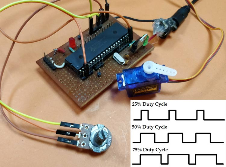
PWM信号生成是每个嵌入式工程师工具库中的重要工具,它们非常适用于控制伺服电机位置,在转换器/逆变器中切换少量电源电子集成电路等许多应用,甚至用于简单的LED亮度控制。在pic 微控制器中, pwm 信号可以通过设置所需的寄存器使用比较、捕获和 pwm (ccp) 模块生成。 如果我们使用CCP模块,PIC16F877A 只能在引脚RC1和RC2产生PWM信号,由此我们可能会遇到需要更多引脚来实现PWM功能的情况。例如,我想控制6个RC伺服电机,CCP模块是不行的。于是在这种情况下,我们可以使用定时器模块对GPIO引脚进行编程以产生PWM信号,这样我们就可以产生尽可能多的PWM信号。还可以考虑其他硬件技术,比如使用多路复用器,但是为什么要在通过编程可以实现同样的目标时,还去考虑其他硬件。因此,在本教程中,我们将学习如何将PIC GPIO引脚转换为PWM引脚,并进行测试,我们将在proteus上使用数字示波器进行仿真,同时使用PWM信号控制伺服电机的位置,并调节电位器改变其占空比。 什么是PWM信号? 在我们详细介绍之前,让我们先了解一下PWM信号是什么。 脉冲宽度调制(PWM) 是一种数字信号,最常用于控制电路。该信号在预定义的时间和速度中设置为高(5v)和低(0v)。信号保持高电平的称为“接通时间” ,信号保持低电平的称为“断开时间”。 如下所述,PWM有两个重要参数: PWM占空比 PWM信号保持高电平(导通时间)的时间百分比称为占空比。如果信号始终为ON,则它处于100%占空比,如果它始终处于关闭状态,则占空比为0%。 PWM的频率
PWM信号的频率决定PWM完成一个周期的速度。一个周期完成PWM信号的ON和OFF,如上图所示。在我们的教程中,我们将设置5KHz的频率。
计算PWM的占空比
要在GPIO引脚上产生PWM信号,我们必须简单地将其打开和关闭一段预定义的时间。但它并不像听起来那么简单。这个打开和关闭时间应该对每个周期都是准确的,因此我们根本不能使用延迟功能,因此我们使用定时器模块定时中断。此外,我们还要考虑占空比和我们生成的PWM信号的频率。程序中使用以下变量名来定义参数。
变量名
指
PWM_Frequency
PWM信号频率
T_TOTAL
PWM的一个完整周期总时间
T_ON
PWM信号的打开时间
T_OFF
PWM信号的关机时间
DUTY_CYCLE
PWM信号占空比 所以现在,让我们做数学。 这是标准公式,其中频率只是时间的倒数。频率值必须由用户根据应用要求来决定和设置。
 模拟
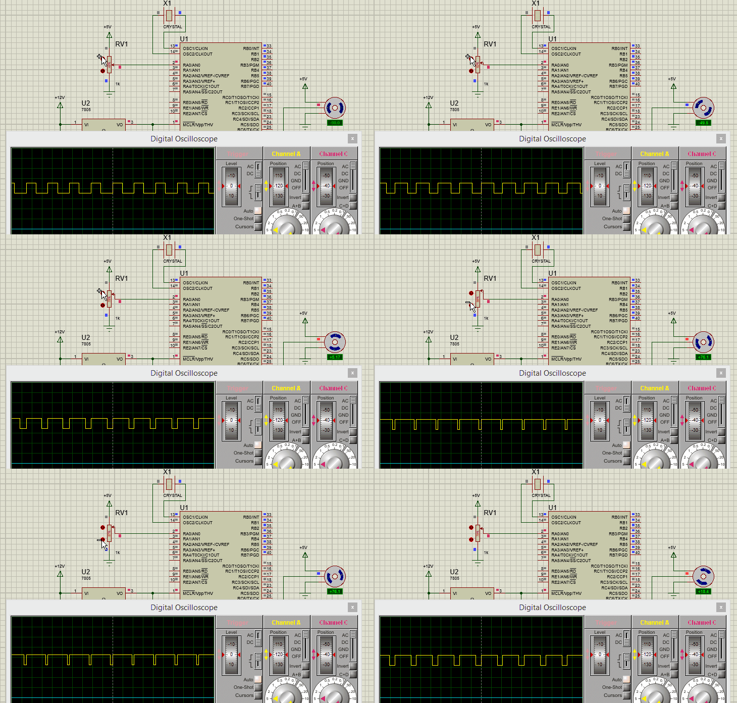
为了模拟项目,我使用了我的proteus软件。构建下面显示的电路并将代码链接到模块并运行它。根据我们的程序, 您应该在RD1 GPIO 引脚上获得PWM 信号, PWM 的占空比应该根据电位器的位置进行控制。下面的GIF 显示了PWM 信号和伺服电机在通过电位器改变ADC值时的响应情况。
Simulation-for-Generating-PWM-signals-on-GPIO-pins-of-PIC-Microcontroller.gif
 使用PIC单片机控制伺服电机的硬件设置
我的完整硬件设置如下所示,对于那些关注我的教程的人来说,这个板应该看起来很熟悉,它与我迄今为止在我所有教程中使用的板相同。
上传程序并更改电位计,您应该看到伺服根据电位计的位置改变而改变位置。
完整代码

PWM信号生成是每个嵌入式工程师工具库中的重要工具,它们非常适用于控制伺服电机位置,在转换器/逆变器中切换少量电源电子集成电路等许多应用,甚至用于简单的LED亮度控制。在pic 微控制器中, pwm 信号可以通过设置所需的寄存器使用比较、捕获和 pwm (ccp) 模块生成。 如果我们使用CCP模块,PIC16F877A 只能在引脚RC1和RC2产生PWM信号,由此我们可能会遇到需要更多引脚来实现PWM功能的情况。例如,我想控制6个RC伺服电机,CCP模块是不行的。于是在这种情况下,我们可以使用定时器模块对GPIO引脚进行编程以产生PWM信号,这样我们就可以产生尽可能多的PWM信号。还可以考虑其他硬件技术,比如使用多路复用器,但是为什么要在通过编程可以实现同样的目标时,还去考虑其他硬件。因此,在本教程中,我们将学习如何将PIC GPIO引脚转换为PWM引脚,并进行测试,我们将在proteus上使用数字示波器进行仿真,同时使用PWM信号控制伺服电机的位置,并调节电位器改变其占空比。 什么是PWM信号? 在我们详细介绍之前,让我们先了解一下PWM信号是什么。 脉冲宽度调制(PWM) 是一种数字信号,最常用于控制电路。该信号在预定义的时间和速度中设置为高(5v)和低(0v)。信号保持高电平的称为“接通时间” ,信号保持低电平的称为“断开时间”。 如下所述,PWM有两个重要参数: PWM占空比 PWM信号保持高电平(导通时间)的时间百分比称为占空比。如果信号始终为ON,则它处于100%占空比,如果它始终处于关闭状态,则占空比为0%。
Duty Cycle =Turn ON time/ (Turn ON time + Turn OFF time)
 PWM的频率
PWM信号的频率决定PWM完成一个周期的速度。一个周期完成PWM信号的ON和OFF,如上图所示。在我们的教程中,我们将设置5KHz的频率。
计算PWM的占空比
要在GPIO引脚上产生PWM信号,我们必须简单地将其打开和关闭一段预定义的时间。但它并不像听起来那么简单。这个打开和关闭时间应该对每个周期都是准确的,因此我们根本不能使用延迟功能,因此我们使用定时器模块定时中断。此外,我们还要考虑占空比和我们生成的PWM信号的频率。程序中使用以下变量名来定义参数。
变量名
PWM的频率
PWM信号的频率决定PWM完成一个周期的速度。一个周期完成PWM信号的ON和OFF,如上图所示。在我们的教程中,我们将设置5KHz的频率。
计算PWM的占空比
要在GPIO引脚上产生PWM信号,我们必须简单地将其打开和关闭一段预定义的时间。但它并不像听起来那么简单。这个打开和关闭时间应该对每个周期都是准确的,因此我们根本不能使用延迟功能,因此我们使用定时器模块定时中断。此外,我们还要考虑占空比和我们生成的PWM信号的频率。程序中使用以下变量名来定义参数。
变量名指
PWM_Frequency
PWM信号频率
T_TOTAL
PWM的一个完整周期总时间
T_ON
PWM信号的打开时间
T_OFF
PWM信号的关机时间
DUTY_CYCLE
PWM信号占空比 所以现在,让我们做数学。 这是标准公式,其中频率只是时间的倒数。频率值必须由用户根据应用要求来决定和设置。
T_TOTAL = (1/PWM_Frequency)
当用户更改占空比值时,我们的程序应自动调整T_ON时间和T_OFF时间。因此,上述公式可用于 根据Duty_Cycle和T_TOTAL的值计算T_ON。
T_ON = (Duty_Cycle*T_TOTAL)/100
由于一个完整周期的PWM信号的总时间将是导通时间和关断时间的总和。我们可以 计算关闭时间T_OFF, 如上所示。
T_OFF = T_TOTAL – T_ON
鉴于这些公式,我们可以开始编程PIC单片机。该程序涉及PIC定时器模块 和PIC ADC模块 ,根据POT的ADC值,根据变化的占空比创建PWM信号。
编程PIC在GPIO引脚上生成PWM
在本节中,让我们了解程序的实际编写方式。像所有程序一样,我们首先设置配置位。我已经使用了memory views选项为我设置它。
// CONFIG
#pragma config FOSC = HS        // Oscillator Selection bits (HS oscillator)

#pragma config WDTE = OFF       // Watchdog Timer Enable bit (WDT disabled)

#pragma config PWRTE = OFF      // Power-up Timer Enable bit (PWRT disabled)

#pragma config BOREN = ON      // Brown-out Reset Enable bit (BOR enabled)

#pragma config LVP = OFF        // Low-Voltage (Single-Supply) In-Circuit Serial Programming Enable bit (RB3 is digital I/O, HV on MCLR must be used for programming)

#pragma config CPD = OFF        // Data EEPROM Memory Code Protection bit (Data EEPROM code protection off)

#pragma config WRT = OFF        // Flash Program Memory Write Enable bits (Write protection off; all program memory may be written to by EECON control)

#pragma config CP = OFF         // Flash Program Memory Code Protection bit (Code protection off)

// #pragma config statements should precede project file includes.

// Use project enums instead of #define for ON and OFF.

#include
然后我们 提到在硬件中使用的时钟频率,这里我的硬件使用20MHz晶振,你可以根据你的硬件输入值。 接下来是PWM信号的频率值。 由于我的目标是控制一个需要PWM频率为50Hz的RC伺服电机,我已将0.05KHz设置为频率值,您也可以根据您的应用要求更改此值。
#define _XTAL_FREQ 20000000

#define PWM_Frequency 0.05 // in KHz (50Hz)
现在,我们有频率值,我们可以使用上面讨论的公式, 计算出T_TOTAL, 结果除以10以后,得到以毫秒为单位的时间值。在我的情况下,T_TOTAL的值将是2毫秒。
int T_TOTAL = (1/PWM_Frequency)/10; //calculate Total Time from frequency (in milli sec)) //2msec
接下来,我们初始化ADC模块以读取电位计的位置。现在让我们检查一下main函数。
在主函数内部,我们配置定时器模块。这里我将Timer模块配置为每0.1ms溢出一次。可以使用下面的公式计算时间的值。
RegValue = 256-((Delay * Fosc)/(Prescalar*4)) delay in sec and Fosc in hz
在我的情况下,延迟为0.0001秒(0.1ms),预分频为64,Fosc为20MHz,我的寄存器(TMR0)的值应该是248,所以配置看起来像这样
/*****Port Configuration for Timer ******/
OPTION_REG = 0b00000101;  // Timer0 with external freq and 64 as prescalar // Also Enables PULL UPs

TMR0=248;       // Load the time value for 0.0001s; delayValue can be between 0-256 only

TMR0IE=1;       //Enable timer interrupt bit in PIE1 register

GIE=1;          //Enable Global Interrupt

PEIE=1;         //Enable the Peripheral Interrupt

/***********______***********/
我们必须设置输入和输出配置。这里我们使用AN0引脚读取ADC值,使用PORTD引脚输出PWM信号。因此,将它们作为输出引脚启动,并使用下面的代码行使它们变低。
/*****Port Configuration for I/O ******/
TRISD = 0x00; //Instruct the MCU that all pins on PORT D are output

PORTD=0x00; //Initialize all pins to 0
/***********______***********/
在while无线循环中,我们要计算占空比中T_ON的时间。导通时间 和占空比根据POT的位置变化,因此我们在 while 循环内重复执行,如下所示。0.0976是必须乘以1024得到100并且计算T_ON的值,我们将它乘以10以得到毫秒的值。
while(1)

      {

      POT_val = (ADC_Read(0)); //Read the value of POT using ADC

            Duty_cycle = (POT_val * 0.0976); //Map 0 to 1024 to 0 to 100

            T_ON = ((Duty_cycle * T_TOTAL)*10 / 100); //Calculate On Time using formulae unit in milli seconds

             __delay_ms(100);

         }
由于定时器每隔0.1ms设置为溢出, 定时器中断服务程序ISR将每0.1ms调用一次。在服务程序中,我们使用一个名为count的变量,每0.1ms递增一次。这样我们就可以跟踪时间。
if(TMR0IF==1) // Timer flag has been triggered due to timer overflow -> set to overflow for every 0.1ms

{

    TMR0 = 248;     //Load the timer Value

    TMR0IF=0;       // Clear timer interrupt flag

     count++; //Count increments for every 0.1ms -> count/10 will give value of count in ms

 }
最后,可以根据T_ON和T_OFF的值切换GPIO引脚。我们有 count 变量,以毫秒为单位跟踪时间。因此我们使用该变量来检查时间是否小于导通时间,如果是,那么我们将GPIO引脚保持打开,否则我们将其关闭,并保持关闭直到新周期开始。这可以通过将其与一个PWM周期的总时间进行比较来完成。相同的代码如下所示
if (count <= (T_ON) ) //If time less than on time

         RD1=1; //Turn on GPIO

    else

          RD1=0; //Else turn off GPIO

     if (count >= (T_TOTAL*10) ) //Keep it turned off until a new cycle starts

          count=0;
电路图
电路图非常简单,只需用振荡器为PIC供电,并将电位器连接到引脚AN0和伺服电机连接到引脚RD1,我们就可以使用GPIO引脚获取PWM信号,我选择RD1只是随机的。电位器和伺服电机均由5V供电,由7805调节,如下图所示。 模拟
为了模拟项目,我使用了我的proteus软件。构建下面显示的电路并将代码链接到模块并运行它。根据我们的程序, 您应该在RD1 GPIO 引脚上获得PWM 信号, PWM 的占空比应该根据电位器的位置进行控制。下面的GIF 显示了PWM 信号和伺服电机在通过电位器改变ADC值时的响应情况。
Simulation-for-Generating-PWM-signals-on-GPIO-pins-of-PIC-Microcontroller.gif
 使用PIC单片机控制伺服电机的硬件设置
我的完整硬件设置如下所示,对于那些关注我的教程的人来说,这个板应该看起来很熟悉,它与我迄今为止在我所有教程中使用的板相同。
上传程序并更改电位计,您应该看到伺服根据电位计的位置改变而改变位置。
完整代码
/*
* File:   PIC_GPIO_PWM.c
* Author: Aswinth
*
* Created on 17 October, 2018, 11:59 AM
*/
// CONFIG
#pragma config FOSC = HS        // Oscillator Selection bits (HS oscillator)
#pragma config WDTE = OFF       // Watchdog Timer Enable bit (WDT disabled)
#pragma config PWRTE = OFF      // Power-up Timer Enable bit (PWRT disabled)
#pragma config BOREN = ON       // Brown-out Reset Enable bit (BOR enabled)
#pragma config LVP = OFF        // Low-Voltage (Single-Supply) In-Circuit Serial Programming Enable bit (RB3 is digital I/O, HV on MCLR must be used for programming)
#pragma config CPD = OFF        // Data EEPROM Memory Code Protection bit (Data EEPROM code protection off)
#pragma config WRT = OFF        // Flash Program Memory Write Enable bits (Write protection off; all program memory may be written to by EECON control)
#pragma config CP = OFF         // Flash Program Memory Code Protection bit (Code protection off)
// #pragma config statements should precede project file includes.
// Use project enums instead of #define for ON and OFF.
#include
#define _XTAL_FREQ 20000000
#define PWM_Frequency 0.05 // in KHz (50Hz)
//TIMER0    8-bit  with 64-bit Prescalar
//$$RegValue = 256-((Delay * Fosc)/(Prescalar*4))  delay in sec and Fosc in hz  ->Substitute value of Delay for calculating RegValue
int POT_val; //variable to store value from ADC
int count; //timer variable
int T_TOTAL = (1/PWM_Frequency)/10; //calculate Total Time from frequency (in milli sec)) //2msec
int T_ON=0; //value of on time
int Duty_cycle; //Duty cycle value
void ADC_Initialize() //Prepare the ADC module
{
 ADCON0 = 0b01000001; //ADC ON and Fosc/16 is selected
 ADCON1 = 0b11000000; // Internal reference voltage is selected
}
unsigned int ADC_Read(unsigned char channel) //Read from ADC
{
 ADCON0 &= 0x11000101; //Clearing the Channel Selection Bits
 ADCON0 |= channel<<3; //Setting the required Bits
 __delay_ms(2); //Acquisition time to charge hold capacitor
 GO_nDONE = 1; //Initializes A/D Conversion
 while(GO_nDONE); //Wait for A/D Conversion to complete
 return ((ADRESH<<8)+ADRESL); //Returns Result
}
void interrupt timer_isr()
{
   if(TMR0IF==1) // Timer flag has been triggered due to timer overflow -> set to overflow for every 0.1ms
   {
       TMR0 = 248;     //Load the timer Value
       TMR0IF=0;       // Clear timer interrupt flag
       count++; //Count increments for every 0.1ms -> count/10 will give value of count in ms
   }

   if (count <= (T_ON) )
       RD1=1;
   else
       RD1=0;

   if (count >= (T_TOTAL*10) )
       count=0;
}
void main()
{
/*****Port Configuration for Timer ******/
   OPTION_REG = 0b00000101;  // Timer0 with external freq and 64 as prescalar // Also Enables PULL UPs
   TMR0=248;       // Load the time value for 0.0001s; delayValue can be between 0-256 only
   TMR0IE=1;      //Enable timer interrupt bit in PIE1 register
   GIE=1;          //Enable Global Interrupt
   PEIE=1;         //Enable the Peripheral Interrupt
   /***********______***********/
   /*****Port Configuration for I/O ******/
   TRISD = 0x00; //Instruct the MCU that all pins on PORT D are output
   PORTD=0x00; //Initialize all pins to 0
   /***********______***********/

   ADC_Initialize();
   while(1)
   {
      POT_val = (ADC_Read(0)); //Read the value of POT using ADC

      Duty_cycle = (POT_val * 0.0976); //Map 0 to 1024 to 0 to 100

      T_ON = ((Duty_cycle * T_TOTAL)*10 / 100); //Calculate On Time using formulae unit in milli seconds
      __delay_ms(100);

   }

}