操作GPIO点灯核心板LD1、LD2可以使用(当然在此之前要step 1:PLL, WatchDog, enable Peripheral Clocks;step 2:Clear all interrupts and initialize PIE vector table;
step3:然后就是GPIO配置)
1、GPBDAT 数据寄存器
配置GPIO复用(对应寄存器GPAMUX2)为GPIO功能 配置GPIO为输出(GPBDIR)默认为输入,0为输入,1为输出 函数中配置GPBDAT为1高电平,延时,在为0低电平,延时(如果配置GPIO为输入模式,GPBDAT为1时锁存,而不输出)

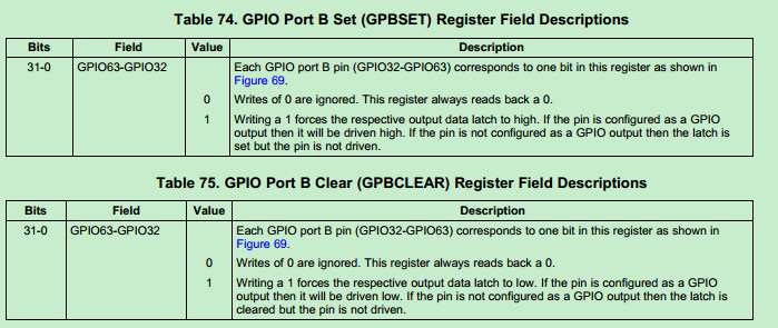
2、GPBSET/GPBCLEAR 设置 / 清除寄存器 这两个寄存器设置为0不起错用,设置为1时起作用,GPBSET为1,驱动输出高电平,GPBCLEAR为1,,驱动清低电平 3、GPATOGGLE 反转寄存器
为0时不起作用,为1时反转当前状态

配置GPIO复用(对应寄存器GPAMUX2)为GPIO功能 配置GPIO为输出(GPBDIR)默认为输入,0为输入,1为输出 函数中配置GPBDAT为1高电平,延时,在为0低电平,延时(如果配置GPIO为输入模式,GPBDAT为1时锁存,而不输出)


2、GPBSET/GPBCLEAR 设置 / 清除寄存器 这两个寄存器设置为0不起错用,设置为1时起作用,GPBSET为1,驱动输出高电平,GPBCLEAR为1,,驱动清低电平
 3、GPATOGGLE 反转寄存器
为0时不起作用,为1时反转当前状态

#include "DSP28x_Project.h"     // Device Headerfile and Examples Include File

// Select the example to compile in.  Only one example should be set as 1
// the rest should be set as 0.
#define EXAMPLE1 0  // Use DATA registers to toggle I/O's
#define EXAMPLE2 0  // Use SET/CLEAR registers to toggle I/O's
#define EXAMPLE3 1  // Use TOGGLE registers to toggle I/O's


// Prototype statements for functions found within this file.
void delay_loop(void);
void Gpio_select(void);
void Gpio_example1(void);
void Gpio_example2(void);
void Gpio_example3(void);

void main(void)
{

// Step 1. Initialize System Control:
// PLL, WatchDog, enable Peripheral Clocks
// This example function is found in the DSP2833x_SysCtrl.c file.
   InitSysCtrl();

// Step 2. Initalize GPIO:
// This example function is found in the DSP2833x_Gpio.c file and
// illustrates how to set the GPIO to it's default state.
// InitGpio();  // Skipped for this example

// For this example use the following configuration:
   Gpio_select();

// Step 3. Clear all interrupts and initialize PIE vector table:
// Disable CPU interrupts
   DINT;

// Initialize PIE control registers to their default state.
// The default state is all PIE interrupts disabled and flags
// are cleared.
// This function is found in the DSP2833x_PieCtrl.c file.
   InitPieCtrl();

// Disable CPU interrupts and clear all CPU interrupt flags:
   IER = 0x0000;
   IFR = 0x0000;

// Initialize the PIE vector table with pointers to the shell Interrupt
// Service Routines (ISR).
// This will populate the entire table, even if the interrupt
// is not used in this example.  This is useful for debug purposes.
// The shell ISR routines are found in DSP2833x_DefaultIsr.c.
// This function is found in DSP2833x_PieVect.c.
   InitPieVectTable();


// Step 4. Initialize all the Device Peripherals:
// This function is found in DSP2833x_InitPeripherals.c
// InitPeripherals(); // Not required for this example

// Step 5. User specific code:

#if EXAMPLE1

    // This example uses DATA registers to toggle I/O's
    Gpio_example1();

#endif  // - EXAMPLE1

#if EXAMPLE2

    // This example uses SET/CLEAR registers to toggle I/O's
    Gpio_example2();

#endif

#if EXAMPLE3

    // This example uses TOGGLE registers to toggle I/O's
    Gpio_example3();

#endif

}

void delay_loop()
{
    volatile long i;
    for (i = 0; i < 1000000; i++) {}
}


void Gpio_example1(void)
{
   // Example 1:
   // Toggle I/Os using DATA registers
   // GPIO7 is used for buzzer
   for(;;)
   {
	   //LD3 ->  GPIO32
	   //LD1/2  ->GPIO60/61
   //    GpioDataRegs.GPADAT.all    =0xAAAAAAAA;   // 1010  A
       GpioDataRegs.GPBDAT.all    =0x3000000A;   // 32-63
       delay_loop();

  //     GpioDataRegs.GPADAT.all    =0x55555555; 	// 0101  5
       GpioDataRegs.GPBDAT.all    =0x00000005;

       delay_loop();
    }
}

void Gpio_example2(void)
{
   // Example 2:
   // Toggle I/Os using SET/CLEAR registers
   for(;;)
   {

       GpioDataRegs.GPASET.all    =0xAAAAAAAA;
       GpioDataRegs.GPACLEAR.all  =0x55555555;  // set/clear register 1 is work

       GpioDataRegs.GPBSET.all    =0x3000000A;
       GpioDataRegs.GPBCLEAR.all  =0x00000005;

       delay_loop();

       GpioDataRegs.GPACLEAR.all    =0xAAAAAAAA;
       GpioDataRegs.GPASET.all      =0x55555555;

       GpioDataRegs.GPBCLEAR.all    =0x3000000A;
       GpioDataRegs.GPBSET.all      =0x00000005;

       delay_loop();

    }
}

void Gpio_example3(void)
{
   // Example 2:
   // Toggle I/Os using TOGGLE registers

   // Set pins to a known state

      GpioDataRegs.GPASET.all    =0xAAAAAAAA;
      GpioDataRegs.GPACLEAR.all  =0x55555555;

      GpioDataRegs.GPBSET.all    =0x3000000A;
      GpioDataRegs.GPBCLEAR.all  =0x00000005;

   // Use TOGGLE registers to flip the state of
   // the pins.
   // Any bit set to a 1 will flip state (toggle)
   // Any bit set to a 0 will not toggle.

   for(;;)
   {
      GpioDataRegs.GPATOGGLE.all =0xFFFFFFFF;
      GpioDataRegs.GPBTOGGLE.all =0x3000000F;
      delay_loop();
    }
}


void Gpio_select(void)
{


    EALLOW;
	GpioCtrlRegs.GPAMUX1.all = 0x00000000;  // All GPIO
	GpioCtrlRegs.GPAMUX2.all = 0x00000000;  // All GPIO
	//GpioCtrlRegs.GPAMUX1.all = 0x00000000;  // All GPIO
    GpioCtrlRegs.GPADIR.all = 0xFFFFFFFF;   // All outputs
    GpioCtrlRegs.GPBDIR.all = 0x3000000F;   // All outputs
    EDIS;

}