刚游泳回来,看到昨晚那篇博客访问量比较高,对我是莫大的鼓励,所以马不停蹄的去找了相关的手册准备我们今天的课程。
今天我们要说的是用定时器0产生的定时中断让LED闪烁。
大家都是大部分都是工科出身,应该都学过单片机,单片机也有定时器,跟我们DSP原理都是类似的,但有一点不同:单片机的定时器是加计数器,也就是装载一个预值后,在这个值的基础上进行递加,直到溢出产生中断;我们这款DSP芯片是减计数器,装载预值后,在时钟的基础上进行递减,直到减到0的下一个时钟产生中断。
类似毕竟类似,不是完全一样,我们现在来具体看下F28027的定时器。
我们在中断那节课的时候,96个中断是如何分布的,现在我们回顾下三个定时器
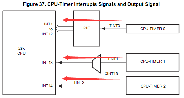
现在来介绍三个定时器和工作流程图:
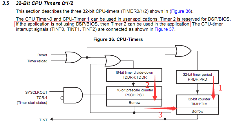
三个定时器没有太大的区别,就是定时器2是为DSP/BIOS保留,如果DSP/BIOS没有使用,定时器2也可以当成通用定时器来处理。
定时器的工作流程其实上面那个图已经很好的解释了,我来复述下:
1、如图左上角那个或门,当CPU复位或者有定时器装载信号的时候,模块1就会收到一个装载信号,会把32位寄存器PRDH:PRD的值填充到TIMH:TIM寄存器中;模块2也会收到这个装载信号,会把16位寄存器TDDRH:TDDR的值填充到PSCH:PSC寄存器中;
2、如果左侧的与门,当TCR寄存器的第五位(定时器启动位)开启时,SYSCLKOUT时钟信号就是送到16位PSCH:PSC寄存器中进行减计数;
3、当PSCH:PSC寄存器的值减到0时,会产生一个中断信号,这个中断信号分两路走:一个是送往TDDRH:TDDR寄存器,使TDDRH:TDDR寄存器的值自动装载到PSCH:PSC寄存器;另一个是当做时钟信号送往TIMH:TIM寄存器做减计数;
4、当TIMH:TIM寄存器的值减到0时,会产生一个中断信号,这个中断信号分两路走:一个是送往PRDH:PRD寄存器,使PRDH:PRD寄存器的值自动装载到TIMH:TIM寄存器;另一个是直接成为系统定时中断信号输出。
怎么样,听我一讲,大家是不是对这个图有了非常清晰的认识,呵呵,最后再来一幅图加固下理解:
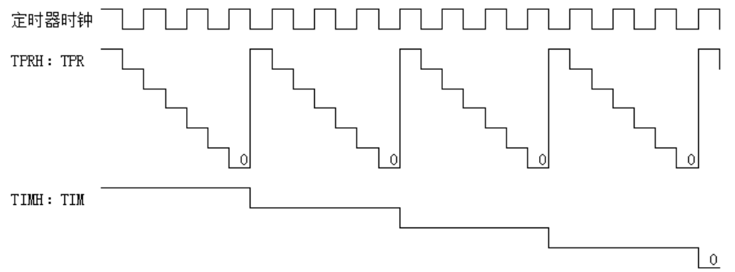
所以定时器的定时时间T=(TIMH:TIM+1)(PRDH:PRD+1)定时器的输入时钟
现在原理性的东西已经讲完了,我们就要开始了解具体的寄存器操作和使用了。
先来看寄存器,其实我们刚才已经把寄存器的使用大概都已经讲了,现在当做温习了。
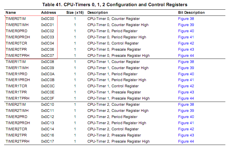
这是总的寄存器说明表,是不是相对比较少,而且就一个控制寄存器TCR,其他都是定时器装载寄存器。
那就从TCR开始了解:
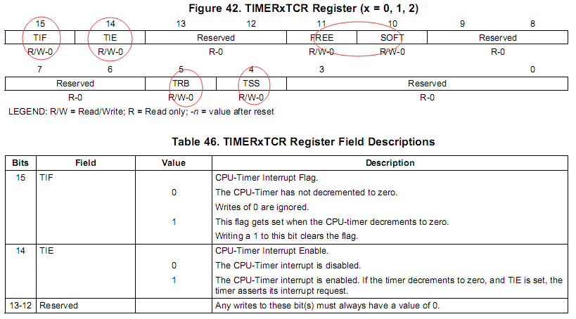
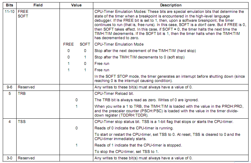
本来想只标一个圈圈的,可是看了寄存器位值说明后,发现每一位都很重要。。
TIF-中断标识位,TIE-中断使能位,FREE:SOFT-仿真模式,TRB-中断定时器值加载位,TSS-停止状态位。
说完TCR,其他几个装载寄存器就直接贴图了,这个没什么好讲的。
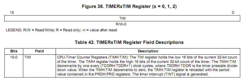
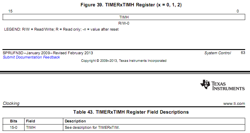


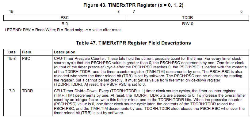

在这里大家需要注意后面那两个TPR/TPRH寄存器,由于TDDRH:TDDR和PSCH:PSC寄存器是16位寄存器,每段是8位,现在是PSCH和TDDRH的值储存在TPRH中,PSC和TDDR的值储存在TPR中,跟前面几个32位寄存器不一样。
现在寄存器也讲完了,现在到我们最刺激的开发环节。
首先,还是要讲流程,有了流程,有了规划,才好做事。我来大概说下定时器使用流程:
1、规划。这个规划既包括PRDH/PRD/TDDRH/TDDR的规划,也包括定时器和时钟的规划;
2、编写定时中断函数,并将该函数指向中断矢量表,这里要注意清楚中断标识PIEACK对应的位,这个是CPU不能自动清除的想;
3、相应的中断设置;
4、启动定时器,装载定时器的值,并开始计数;
5、打开中断组开关和总开关,开始程序的运行。
好了,思路也理清楚了,现在开始准备写程序,先准备本次需要的文件,既然是定时器,那我们就需要把TI提供的F2802x_CpuTimers.c文件从C: icontrolSUITEdevice_supportf2802xv200f2802x_commonsource路径拷贝到D:studyday002projectsrc目录下,其他所有的文件,跟昨天一样,新建工程和工程设置这一步我们就直接跳过了。
由于我们还是使用昨天的Proteus仿真文件,端口也不变,所以GPIO.c文件今天就不动了,跟昨天保持一样。
至于定时周期,我还是想跟昨天延时函数时间一致,都是1ms,那我们现在就来算一下。
公式是T=(TIMH:TIM+1)(PRDH:PRD+1)定时器的输入时钟,现在T=0.001,时钟跟系统时钟一致60MHZ,也就是1/60000000,所以(TIMH:TIM+1)*(PRDH:PRD+1)=60000,而PRD寄存器是16位,TIM是32位,所以(PRDH:PRD+1)设为60,(TIMH:TIM+1)设为1000。好了,可以开始写程序了。
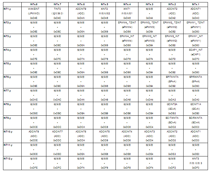
看到了吧,TINT0在第一个中断组的第七位,也就是INT1.7位
现在先去写中断函数,中断函数直接去TI提供的F2802x_DefaultIsr.c文件修改就行了,修改后如图:
真高兴,又是两个小时过去了,吃饭,吃晚饭回来我们继续做外部中断触发,敬请期待!
菜鸟交流qq群107691092
今天我们要说的是用定时器0产生的定时中断让LED闪烁。
大家都是大部分都是工科出身,应该都学过单片机,单片机也有定时器,跟我们DSP原理都是类似的,但有一点不同:单片机的定时器是加计数器,也就是装载一个预值后,在这个值的基础上进行递加,直到溢出产生中断;我们这款DSP芯片是减计数器,装载预值后,在时钟的基础上进行递减,直到减到0的下一个时钟产生中断。
类似毕竟类似,不是完全一样,我们现在来具体看下F28027的定时器。
我们在中断那节课的时候,96个中断是如何分布的,现在我们回顾下三个定时器

现在来介绍三个定时器和工作流程图:

三个定时器没有太大的区别,就是定时器2是为DSP/BIOS保留,如果DSP/BIOS没有使用,定时器2也可以当成通用定时器来处理。
定时器的工作流程其实上面那个图已经很好的解释了,我来复述下:
1、如图左上角那个或门,当CPU复位或者有定时器装载信号的时候,模块1就会收到一个装载信号,会把32位寄存器PRDH:PRD的值填充到TIMH:TIM寄存器中;模块2也会收到这个装载信号,会把16位寄存器TDDRH:TDDR的值填充到PSCH:PSC寄存器中;
2、如果左侧的与门,当TCR寄存器的第五位(定时器启动位)开启时,SYSCLKOUT时钟信号就是送到16位PSCH:PSC寄存器中进行减计数;
3、当PSCH:PSC寄存器的值减到0时,会产生一个中断信号,这个中断信号分两路走:一个是送往TDDRH:TDDR寄存器,使TDDRH:TDDR寄存器的值自动装载到PSCH:PSC寄存器;另一个是当做时钟信号送往TIMH:TIM寄存器做减计数;
4、当TIMH:TIM寄存器的值减到0时,会产生一个中断信号,这个中断信号分两路走:一个是送往PRDH:PRD寄存器,使PRDH:PRD寄存器的值自动装载到TIMH:TIM寄存器;另一个是直接成为系统定时中断信号输出。
怎么样,听我一讲,大家是不是对这个图有了非常清晰的认识,呵呵,最后再来一幅图加固下理解:

所以定时器的定时时间T=(TIMH:TIM+1)(PRDH:PRD+1)定时器的输入时钟
现在原理性的东西已经讲完了,我们就要开始了解具体的寄存器操作和使用了。
先来看寄存器,其实我们刚才已经把寄存器的使用大概都已经讲了,现在当做温习了。

这是总的寄存器说明表,是不是相对比较少,而且就一个控制寄存器TCR,其他都是定时器装载寄存器。
那就从TCR开始了解:


本来想只标一个圈圈的,可是看了寄存器位值说明后,发现每一位都很重要。。
TIF-中断标识位,TIE-中断使能位,FREE:SOFT-仿真模式,TRB-中断定时器值加载位,TSS-停止状态位。
说完TCR,其他几个装载寄存器就直接贴图了,这个没什么好讲的。


在这里大家需要注意后面那两个TPR/TPRH寄存器,由于TDDRH:TDDR和PSCH:PSC寄存器是16位寄存器,每段是8位,现在是PSCH和TDDRH的值储存在TPRH中,PSC和TDDR的值储存在TPR中,跟前面几个32位寄存器不一样。
现在寄存器也讲完了,现在到我们最刺激的开发环节。
首先,还是要讲流程,有了流程,有了规划,才好做事。我来大概说下定时器使用流程:
1、规划。这个规划既包括PRDH/PRD/TDDRH/TDDR的规划,也包括定时器和时钟的规划;
2、编写定时中断函数,并将该函数指向中断矢量表,这里要注意清楚中断标识PIEACK对应的位,这个是CPU不能自动清除的想;
3、相应的中断设置;
4、启动定时器,装载定时器的值,并开始计数;
5、打开中断组开关和总开关,开始程序的运行。
好了,思路也理清楚了,现在开始准备写程序,先准备本次需要的文件,既然是定时器,那我们就需要把TI提供的F2802x_CpuTimers.c文件从C: icontrolSUITEdevice_supportf2802xv200f2802x_commonsource路径拷贝到D:studyday002projectsrc目录下,其他所有的文件,跟昨天一样,新建工程和工程设置这一步我们就直接跳过了。
由于我们还是使用昨天的Proteus仿真文件,端口也不变,所以GPIO.c文件今天就不动了,跟昨天保持一样。
至于定时周期,我还是想跟昨天延时函数时间一致,都是1ms,那我们现在就来算一下。
公式是T=(TIMH:TIM+1)(PRDH:PRD+1)定时器的输入时钟,现在T=0.001,时钟跟系统时钟一致60MHZ,也就是1/60000000,所以(TIMH:TIM+1)*(PRDH:PRD+1)=60000,而PRD寄存器是16位,TIM是32位,所以(PRDH:PRD+1)设为60,(TIMH:TIM+1)设为1000。好了,可以开始写程序了。
void InitCpuTimers(void)
{
    // CPU Timer 0
    // Initialize address pointers to respective timer registers:
    CpuTimer0.RegsAddr = &CpuTimer0Regs;
    // Initialize timer period to maximum:
    CpuTimer0Regs.PRD.all  = 999;
    // Initialize pre-scale counter to divide by 1 (SYSCLKOUT):
    CpuTimer0Regs.TPR.bit.TDDR  = 59;
    CpuTimer0Regs.TPRH.bit.TDDRH = 0;
    // Make sure timer is stopped:
    CpuTimer0Regs.TCR.bit.TSS = 1;
    // Reload all counter register with period value:
    CpuTimer0Regs.TCR.bit.TRB = 1;
    // Reset interrupt counters:
    CpuTimer0.InterruptCount = 0;

// CpuTimer 1 and CpuTimer2 are reserved for DSP BIOS & other RTOS
// Do not use these two timers if you ever plan on integrating
// DSP-BIOS or another realtime OS.
//
// Initialize address pointers to respective timer registers:
    CpuTimer1.RegsAddr = &CpuTimer1Regs;
    CpuTimer2.RegsAddr = &CpuTimer2Regs;
    // Initialize timer period to maximum:
    CpuTimer1Regs.PRD.all  = 0xFFFFFFFF;
    CpuTimer2Regs.PRD.all  = 0xFFFFFFFF;
    // Initialize pre-scale counter to divide by 1 (SYSCLKOUT):
    CpuTimer1Regs.TPR.all  = 0;
    CpuTimer1Regs.TPRH.all = 0;
    CpuTimer2Regs.TPR.all  = 0;
    CpuTimer2Regs.TPRH.all = 0;
    // Make sure timers are stopped:
    CpuTimer1Regs.TCR.bit.TSS = 1;
    CpuTimer2Regs.TCR.bit.TSS = 1;
    // Reload all counter register with period value:
    CpuTimer1Regs.TCR.bit.TRB = 1;
    CpuTimer2Regs.TCR.bit.TRB = 1;
    // Reset interrupt counters:
    CpuTimer1.InterruptCount = 0;
    CpuTimer2.InterruptCount = 0;

}
定时器初始化函数如上所示,现在开始写中断了,回顾下,大家还记得定时中断0 TINT0在哪个PIE中断组吗 
看到了吧,TINT0在第一个中断组的第七位,也就是INT1.7位
现在先去写中断函数,中断函数直接去TI提供的F2802x_DefaultIsr.c文件修改就行了,修改后如图:
interrupt void  TINT0_ISR(void)      // CPU-Timer 0
{
  // Insert ISR Code here
    GpioDataRegs.GPATOGGLE.all=0x000000ff;
  // To receive more interrupts from this PIE group, acknowledge this interrupt
    PieCtrlRegs.PIEACK.all = PIEACK_GROUP1;

  // Next two lines for debug only to halt the processor here
  // Remove after inserting ISR Code
  //asm ("      ESTOP0");
  //for(;;);
}
编写主函数:
void main(void)
{

// Step 1. Initialize System Control:
// PLL, WatchDog, enable Peripheral Clocks
// This example function is found in the DSP2802x_SysCtrl.c file.
   InitSysCtrl();

// Step 2. Initalize GPIO:
// This example function is found in the DSP2802x_Gpio.c file and
// illustrates how to set the GPIO to it's default state.
   InitGpio();

// Step 3. Clear all interrupts and initialize PIE vector table:
// Disable CPU interrupts
   DINT;

// Initialize PIE control registers to their default state.
// The default state is all PIE interrupts disabled and flags
// are cleared.
// This function is found in the DSP2802x_PieCtrl.c file.
   InitPieCtrl();

// Disable CPU interrupts and clear all CPU interrupt flags:
   IER = 0x0000;
   IFR = 0x0000;

// Initialize the PIE vector table with pointers to the shell Interrupt
// Service Routines (ISR).
// This will populate the entire table, even if the interrupt
// is not used in this example.  This is useful for debug purposes.
// The shell ISR routines are found in DSP2802x_DefaultIsr.c.
// This function is found in DSP2802x_PieVect.c.
   InitPieVectTable();


// Step 4. Initialize all the Device Peripherals:
// This function is found in DSP2802x_InitPeripherals.c
// InitPeripherals(); // Not required for this example

// Step 5. User specific code:

   GpioDataRegs.GPADAT.all = 0x00000000;  //GPIO0-GPIO31 initial value are 0

   CpuTimer0Regs.TCR.bit.TIE = 1;
   StartCpuTimer0();
   EALLOW;
   PieCtrlRegs.PIEIER1.bit.INTx7 = 1;
   PieCtrlRegs.PIECTRL.bit.ENPIE = 1;
   IER = 0x0001;
   EINT;
   EDIS;

   while(1)
   {
//     GpioDataRegs.GPATOGGLE.all=0x000000ff;
//       DELAY_US(1000);
   }
}
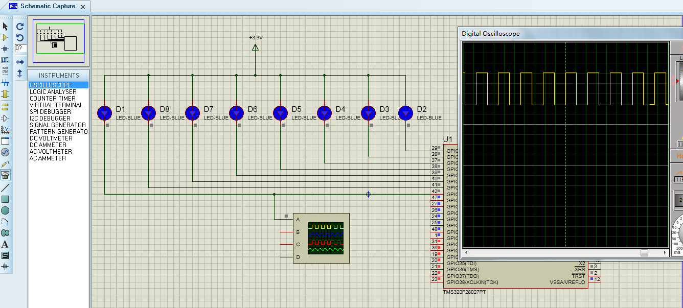
OK,写完了,导入Proteus测试下。测试结果OK,达到预期效果。 
真高兴,又是两个小时过去了,吃饭,吃晚饭回来我们继续做外部中断触发,敬请期待!
菜鸟交流qq群107691092