camera基本代码架构
Camera原理:外部光线穿过lens后,经过color filter滤波后照射到sensor面上,sensor将从lens上传到过来的光线转换成电信号,再通过内部的AD转换为数字信号,如果sensor没有集成DSP,则通过DVP的方式传输到baseband,此时的数据格式是RAW DATA。必须通过平台的isp来处理。如果集成了DSP,这RAW DATA数据经过AWB,color matrix,lens shading,gamma,sharpness,AE和de-noise处理后输出YUV或者RGB格式的数据。最后会由CPU送到framebuffer中进行显示。 1、首先对照原理图,检查camera module的pin脚连接是否正确。
 2、用示波器量Camera的MCLK管脚,看是否正确,如果MCLK正常,通常情况下PCLK也应该有波形;
(1)MCLK 为camera提供时钟,给模组内部的pll使用。qualcomm平台是24MHZ。broadcom平台是26MHZ。
3、用万用表测量Camera的电源管脚,查看Camera的供电是否正常;
(2)AVDD 模拟电路电源 2.8V ,正常情况下,AVDD需要单独供电,电源纹波<=30mV.
IOVDD/DOVDD/VIF: Power support for IO circuits 1.8V
DVDD 数字电路供电电源 1.2V,如果IOVDD是1.8V的话,推荐使用sensor internal DVDD.硬件上就不要做external DVDD,否则将会导致竖条纹问题的出现。
 如果IOVDD是使用2.8V的话,则使用external DVDD,上电时序将改变。
 3、查看Camera的Spec文档,检查PWDN和RESET的管脚触发是否正常;检查代码中camera power up时序是否与datasheet的一致。
(3)RESET/XSHUTDOWN/XCLR:用来reset sensor;RESET一般是低有效,当脉冲为低时,reset sensor,而正常工作时,应该为高。注意reset的时间要求
(4)PWDN/standby:power down引脚,切断供电。即powerdown 有效时,camera 为不工作模式。PWDN一般是高有效,当脉冲为高时,进入省电模式,而正常工作时为低。、powe rdown 有效极性。pwdn高有效就是说pwdn为高电平的时候进入power down模式,所以在进入预览界面的时候就要把pwdn拉低。这样camera才能进入正常工作状态
(5) XCLR is reset input signal and power OFF of internal core, camera become standby situation.(Low active)
XCLR=”H”:Usually situation XCLR=”L”:Reset situation
(6) XSHUTDOWN:reset and power down(active low with internal pull down resistor) hardware reset
(7) sony sensor has the build in power on reset function.It automatically initializes the internal circuit by itself when XCLR pin is open and the power supplies are brought up.In addition,if XCLR pin is set to low and the power supplies are bring up.The sensor will skip executing the power on reset function.
4、在Camera的Datasheet中找出该设备的I2C地址,检查I2C配置是否正确;通常Camera Sensor的Spec上所写的I2C ID号,还包含了最后一位读写方向位。而这一位在I2C总线的定义中,严格来说,不属于ID的一部分,所以Linux I2C的驱动API中的调用参数里的ID号,通常是不考虑这一位的,读写方向位会在具体的读写操作中,在寄存器中进行设置。
5、查看I2C通信是否正常,是否能正常进行读写,用示波器量出I2C的SCL和SDA的波形是否正常,未通信时都为高电平,通信时SCL为I2C时钟信号,SDA为I2C数据通路信号;
6、让Sensor FAE检查Camera的寄存器列表的配置是否正确。
高通平台对于camera的代码组织,大体上还是遵循Android的框架:即上层应用和HAL层交互,高通平台在HAL层里面实现自己的一套管理策略;在kernel中实现sensor的底层驱动。对于最核心的sensor端的底层设置、ISP效果相关等代码则是单独进行了抽离,放在了一个daemon进程中进行管理。
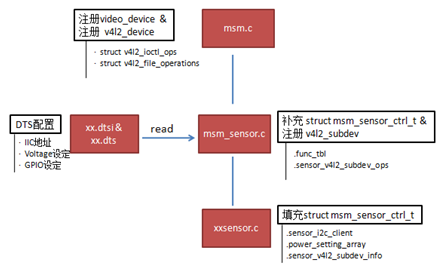 图1 kernel层camera主要代码简图
如上图,camera在kernel层的主文件为msm.c,负责设备的具体注册及相关方法的填充;在msm_sensor.c文件中,主要维护高通自己的一个sensor相关结构体—msm_sensor_ctrl_t,同时把dts文件中的配置信息读取出来;kernel层对于不同的sensor对应自己的一个驱动文件— xxsensor.c,主要是把power setting的设定填充到msm_sensor_ctrl_t中。
在vendor目录下,高通把各个sensor实质性的代码放置在此。一部分代码是高通自己实现的daemon进程和kernel层及HAL层进行通讯的框架代码;另一部分则是和sensor相关的chromatix效果代码和sensor lib部分代码(init setting、lens info、output info)。
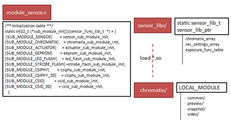 图2 vendor下主要camera代码简图
如上图,高通平台通过一个函数指针数组sub_module_init来管理sensor相关的组件;其中重要的是sensor_sub_module_init和chromatix_sub_module_init模块,对于sensor模块需要对应填充sensor_lib_t下的接口,对于chromatix模块则是通过高通的chromatix工具生成。
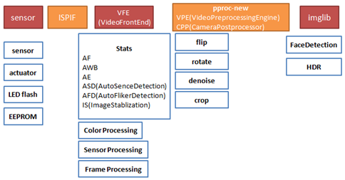 从更高的层次来看,sensor部分的代码只是camera子系统的一部分。打开高通vendor下面关于camera的源码也可以看到,/mm-camera2/media-controller/modules目录下面,sensors只是modules文件下面其中的一个子目录。
2 主要移植步骤
2.1 kernel层代码移植
1. 在./kernel/arch/arm/boot/dts/msm8226-camera-sensor-qrd.dtsi中新增camera节点,重点关注节点中的IIC地址、sensro的ID信息、电压设定信息: qcom,camera@21 { //21 is the I2C slave Id of the imx214 compatible = “qcom,imx214”; //same as the sensor name used in the project reg = <0x21>;qcom,slave-id = <0x20 0x0016 0x0214>; //sensor id
qcom,csiphy-sd-index = <0>;
qcom,csid-sd-index = <0>;
qcom,actuator-src = <&actuator1>;
qcom,led-flash-src = <&led_flash0>;
qcom,eeprom-src = <&eeprom4>;
qcom,mount-angle = <90>; // 90 for rear camera and 270 for front camera
qcom,sensor-name = “imx214”;// unique sensor name to differentiate from other sensor cam_vdig-supply = <&pm8226_l5>;// defined in ./kernel/arch/arm/boot/dts/msm8226-regulator.dtsi
cam_vana-supply = <&pm8226_l15>;
cam_vio-supply = <&pm8226_lvs1>;
cam_vaf-supply = <&pm8226_l18>;
qcom,cam-vreg-name = “cam_vdig”, “cam_vio”, “cam_vana”,”cam_vaf”;
qcom,cam-vreg-type = <0 1 0 0>; // 0 for LDO and 1 for LVS
qcom,cam-vreg-min-voltage = <1100000 1800000 2800000 2950000>;
qcom,cam-vreg-max-voltage = <1100000 1800000 2800000 2950000>;
qcom,cam-vreg-op-mode = <120000 0 200000 600000>;
qcom,gpio-no-mux = <0>;
gpios = <&msmgpio 26 0>,
<&msmgpio 37 0>,
<&msmgpio 36 0>,
<&msmgpio 15 0>;
qcom,gpio-reset = <1>;
qcom,gpio-standby = <2>;
qcom,gpio-af-pwdm = <3>;
qcom,gpio-req-tbl-num = <0 1 2 3>;
qcom,gpio-req-tbl-flags = <1 0 0 0>;
qcom,gpio-req-tbl-label = “CAMIF_MCLK”,
“CAM_RESET1”,
“CAM_STANDBY”,
“CAM_AF_PWDM”;
qcom,csi-lane-assign = <0x4320>;
qcom,csi-lane-mask = <0x1f>;
qcom,sensor-position = <0>; // 0 for rear camea and 1 for front camera
qcom,sensor-mode = <0>; // 0 for bayer format and 1 for yuv format
qcom,cci-master = <0>;
status = “ok”;
}; 详细的文档请参考 ./kernel/Documentation/devicetree/bindings/media/video/目录。 2.增加以下文件./kernel/drivers/media/platform/msm/camera_v2/sensor/imx214.c +static struct msm_sensor_power_setting imx214_power_setting[] = {
+ {
+ .seq_type = SENSOR_VREG,
+ .seq_val = CAM_VIO,
+ .config_val = 0,
+ .delay = 1,
+ },
+ {
+ .seq_type = SENSOR_VREG,
+ .seq_val = CAM_VANA,
+ .config_val = 0,
+ .delay = 1,
+ },
+ {
+ .seq_type = SENSOR_VREG,
+ .seq_val = CAM_VDIG,
+ .config_val = 0,
+ .delay = 1,
+ },
+ {
+ .seq_type = SENSOR_VREG,
+ .seq_val = CAM_VAF,
+ .config_val = 0,
+ .delay = 5,
+ },
+ {
+ .seq_type = SENSOR_GPIO,
+ .seq_val = SENSOR_GPIO_STANDBY,
+ .config_val = GPIO_OUT_LOW,
+ .delay = 1,
+ },
+ {
+ .seq_type = SENSOR_GPIO,
+ .seq_val = SENSOR_GPIO_RESET,
+ .config_val = GPIO_OUT_LOW,
+ .delay = 5,
+ },
+ {
+ .seq_type = SENSOR_GPIO,
+ .seq_val = SENSOR_GPIO_AF_PWDM,
+ .config_val = GPIO_OUT_LOW,
+ .delay = 5,
+ },
+ {
+ .seq_type = SENSOR_GPIO,
+ .seq_val = SENSOR_GPIO_STANDBY,
+ .config_val = GPIO_OUT_HIGH,
+ .delay = 5,
+ },
+ {
+ .seq_type = SENSOR_GPIO,
+ .seq_val = SENSOR_GPIO_RESET,
+ .config_val = GPIO_OUT_HIGH,
+ .delay = 10,
+ },
+ {
+ .seq_type = SENSOR_GPIO,
+ .seq_val = SENSOR_GPIO_AF_PWDM,
+ .config_val = GPIO_OUT_HIGH,
+ .delay = 5,
+ },
+ {
+ .seq_type = SENSOR_CLK,
+ .seq_val = SENSOR_CAM_MCLK,
+ .config_val = 24000000,
+ .delay = 10,
+ },
+ {
+ .seq_type = SENSOR_I2C_MUX,
+ .seq_val = 0,
+ .config_val = 0,
+ .delay = 0,
+ },
+}; 3.在以下文件中添加对imx214的支持 ./kernel/arch/arm/configs/msm8226_defconfig +CONFIG_IMX214=y 4./kernel/drivers/media/platform/msm/camera_v2/Kconfig +config IMX214
+ bool “Sensor IMX214 (BAYER 13M)”
+ depends on MSMB_CAMERA
+ —help—
+ Sony 12 MP Bayer Sensor with auto focus, uses
+ 4 mipi lanes, preview config = 2104 x 1560 at 49 fps,
+ snapshot config = 4208 x 3120 at 24 fps,
+ Video HDR support. 5、./kernel/drivers/media/platform/msm/camera_v2/sensor/Makefile +obj-$(CONFIG_IMX214) += imx214.o 6、注册时钟./kernel/arch/arm/mach-msm/clock-8226.c @@ -3421,6 +3421,11 @@ static struct clk_lookup msm_clocks_8226[] = {
CLK_LOOKUP(“cam_clk”, camss_mclk0_clk.c, “0.qcom,camera”),
CLK_LOOKUP(“cam_clk”, camss_mclk0_clk.c, “1.qcom,camera”),
+ CLK_LOOKUP(“cam_clk”, camss_mclk0_clk.c, “21.qcom,camera”),
+ CLK_LOOKUP(“cam_src_clk”, mclk0_clk_src.c, “21.qcom,camera”),
2.2 vendor下代码移植
Vendor下面的代码主要是两部分,一个是sensor_libs目录下的sensor具体设定、配置文件,另一个是chromatix下面的ISP效果文件。具体为: 1. ./vendor/qcom/proprietary/mm-camera/mm-camera2/media-controller/modules/sensors/sensor_libs/imx214/imx214_lib.c +/*===========================================================================+ * FUNCTION - imx214_open_lib -
+ *
+ * DESCRIPTION:
+ *==========================================================================*/
+void *imx214_open_lib(void)
+{
+ return &sensor_lib_ptr;
+} This lib will be loaded when camera deamon process is started, kernel will find the handle based on the sensor name in dtb(device tree binary file), so please make sure the file name and function name follow the request for your sensor.
void *
{
/* vt_pixel_clk = .line_length_pclk* frame_length_lines*frame rate */
/* op_pixel_clk = VFE working clk */ …. }
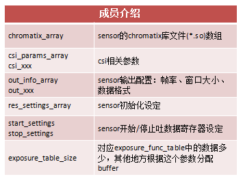 2. chromatix目录下相关文件,在对应sensor目录下包含4个目录和一个Android文件,总共13个文件,这些文件都会由chromatix调试工具生成。
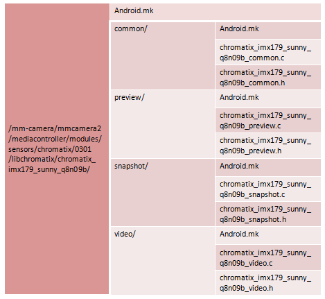 图8 vendor下chromatix相关文件示例图
3. vendor下还有eeprom文件,模组自带的eeprom数据处理相关;AF相关文件,调试工具生成的关于AF的效果文件;配置文件,把需要编译的模块填进配置文件中。
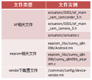 Acuator porting
./kernel/drivers/media/video/msm/actuators/actuator.c
msm_actuator_ctrl_t contains all the information about the actuator setting related to sensors like
 i2c addr, set_info, focal length, etc. All the info is loaded from the chromatix file for the sensor. In af header file, the driver engineer should take care of the structure of actuator_params_t, which contains the af drive ic address, register patten, etc. It is important for AF working.
3 调试常见问题
3.1 kernel和vendor下命名匹配
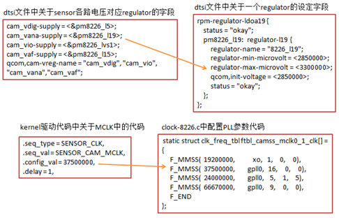
在参考其他代码移植调试一个新sensor的过程中,要注意在对应的dts文件中给sensor配置节点信息的过程中,“qcom,sensor-name”字段的配置要和vendor下面的sensor lib代码中的“xxx_open_lib”函数名以及对应的Android.mk中的“LOCAL_MODULE”名称匹配,否则相应sensor的vendor下库文件无法调用,这时打开camera会出现闪退现象。具体可参考平台代码sensor.c中的sensor_load_library()函数。 图10 camera name匹配详图
3.2 sensor lib中的sensor_lib_out_info_t填充
一般来说,每个sensor可以配置输出不同大小的图像。此时,除了进行对应的sensor setting来改变sensor自身的输出及相关配置外;还需要将相关的输出大小、帧率等信息通知平台端,即填充struct sensor_lib_out_info_t结构体。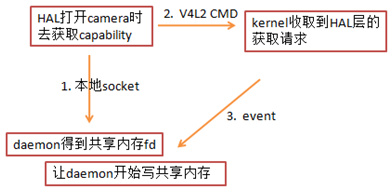 图11 高通平台获取sensor信息框图
填充的这个sensor_lib_out_info_t中的成员,最终会作为sensor基本信息的一部分被HAL层获取到,上图为高通平台获取sensor信息的一个简单框图。
在调试过程中,需要注意的是这个结构体的成员max_fps需要填写至少大于等于30;否则会因为在获取capability时无法得到有效的previewsize、video size而无法进入预览。具体可参考平台代码mct_pipeline.c中的mct_pipeline_populate_query_cap_buffer()函数。
3.3 sensorlib中的exposure_table_size填写
对于sensor端输出RAW数据,平台端进行ISP处理的情形来说,sensor端除了基本的init配置外,另外一个就是根据平台端AEC计算出来的数据来对应调整sensor的曝光。在高通平台上将平台端的AEC和具体的sensor曝光设置联系起来的是chromatix文件中的一个Exposure Table和sensor lib文件中的exposure对应接口。 这里的exposure_table_size对应着sensor lib中sensor_fill_exposure_array()接口写入的sensor寄存器的个数,平台代码中需要根据这个exposure_table_size来动态分配内存大小。如果这个值的填写和sensor_fill_exposure_array()中实际写入的值大小不一致,就会造成内存方面的crash。具体可参考平台代码sensor.c中的sensor_apply_exposure()函数。3.4 kernel 层非常规设定
对于一些sensor来说,对于电压的设定或是MCLK的设定有非常规要求的时候,可能就需要修改平台上相关的默认设定。 对于sensor的几路工作电压 (AVDD、DVDD、IOVDD),平台端一般都是通过PMIC的相应regulator供电,而硬件上regulator的输出能力一般都有限制,代码上也会有体现。如果有sensor需要的电压超过代码上相应regulator的限制值,可以查看PMIC上的说明,如果代码上的限制值并不是硬件的真正极限,可以修改平台代码解决。 对于MCLK的设定,高通平台有一些常规的值设定。如果sensor有特殊要求,而这个MCLK不能被平台识别,这时候可以在平台的clock相关代码中,通过配置平台的PLL参数来生成特定的MCLK时钟给sensor使用。