References:
[1] Understanding cascaded integrator-comb filters – By Richard Lyons, Courtesy of Embedded Systems Programming
URL: http://www.us.design-reuse.com/articles/article10028.html
[2] Example of Cascaded Integrator Comb filter in Matlab http://www.dsplog.com/2007/07/01/example-of-cascaded-integrator-comb-filter-in-matlab/
[3] Digital Signal Processing – Principles, Algorithms and Applications
, John G. Proakis, Dimitris G. Manolakis
CIC数字滤波器是窄带低通滤波器的高计算效率的实现形式,常常被嵌入到现代通信系统的抽取和插值模块的硬件实现中。
CIC filter
应用
CIC滤波器非常适合用作抽取之前的抗混迭滤波和插值之后的抗镜像滤波。这两种应用都跟very high-data-rate滤波有关,例如现代无线系统中硬件正交调制和解调,以及delta-sigma A/D 和 D/A 转换器。
 Figure 1: CIC filter applications
因为CIC滤波器的幅频响应包络象sin(x)/x,通常在CIC滤波器之前或者之后都有一个high-performance linear-phase lowpass tapped-delay-line FIR filters, 用于补偿CIC滤波器不够平坦的通带。
CIC滤波器不需要乘法运算,易于硬件实现。
抽取CIC滤波器只不过是滑动平均滤波器的一个非常高效的迭代实现,有NR
taps, 其输出再进行 R
抽取
. 同样,插值CIC滤波器在每两个输入采样之间插入R
-1个0,然后通过一个NR
-tap的工作在输出采样率ƒs
,out
的滑动平均滤波器。对于高采样率转换率的抽取和插值来说,Figure 1所示的级联形式的计算量大大低于单一FIR滤波器的计算量。
Recursive running-sum filter
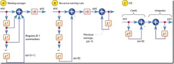
Figure 2: D-point averaging filters Figure 2a是标准的D-point moving-average 处理,需要D-1次加法运算和1次乘法运算。时域表达式: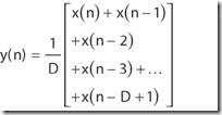
Equation 1 z域表达式:
Equation 2 z域传递函数:
Equation 3 Figure 2b: 迭代running-sum filter,等价于figure 2a. y(n) = 1/D * [x(n) + x(n-1) + … + x(n-D+1)] y(n-1) = 1/D * [x(n-1) + x(n-2) + x(n-D+1) + x(n-D)] y(n) – y(n-1) = 1/D * [x(n) – x(n-D)]
Equation 4 z域传递函数:
Equation 5 Equation 3 和 Equation 5 本质是一样的。Equation 3 是非递归表达式,equation 5是递归表达式。不考虑delay length D的话,递归形式只需要一个加法和一个减法运算。 例子:figure 1a的matlab实现,滑动平均滤波器,忽略scale factor % Moving Average filter
N = 10; %延时
xn = sin(2*pi*[0:.1:10]); %n=[0:1:100]; sin(2*pi*f*t)=sin(2*pi*f*T*n)=>f=1Hz, fs=10Hz.
hn = ones(1,N); %脉冲响应
y1n = conv(xn,hn); % transfer function of Moving Average filter
hF = fft(hn,1024);
plot([-512:511]/1024, abs(fftshift(hF)));
xlabel(’Normalized frequency’)
ylabel(’Amplitude’)
title(’frequency response of Moving average filter’)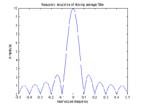 Figure 1c的matlab实现
% Implementing Cascaded Integrator Comb filter with the
% comb section following the integrator stage
N = 10;
delayBuffer = zeros(1,N);
intOut = 0;
xn = sin(2*pi*[0:.1:10]);
for ii = 1:length(xn)
% comb section
combOut = xn(ii) – delayBuffer(end);
delayBuffer(2:end) = delayBuffer(1:end-1);
delayBuffer(1) = xn(ii); % integrator
intOut = intOut + combOut;
y2n(ii) = intOut;
end err12 = y1n(1:length(xn)) – y2n;
err12dB = 10*log10(err12*err12′/length(err12)) % identical outputs
close all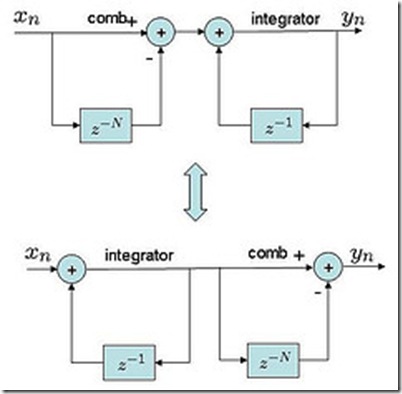 先integrator后comb的实现
% Implementing Cascaded Integrator Comb filter with the
% integrator section following the comb stage N = 10;
delayBuffer = zeros(1,N);
intOut = 0;
xn = sin(2*pi*[0:.1:10]);
for ii = 1:length(xn)
% integrator
intOut = intOut + xn(ii); % comb section
combOut = intOut – delayBuffer(end);
delayBuffer(2:end) = delayBuffer(1:end-1);
delayBuffer(1) = intOut;
y3n(ii) = combOut; end
err13 = y1n(1:length(xn)) – y3n;
err13dB = 10*log10(err13*err13′/length(err13)) % identical outputs CIC filter structures Figure 2c: the classic form of 1st-order CIC filter, 忽略figure 2b中的1/D因子。 其中前馈部分称为comb section, 其differential delay 是D;反馈部分称为积分器。 差分方程:
Equation 6
Equation 7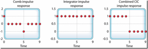
Figure 3: Single-stage CIC filter time-domain responses when D = 5 Figure 2c这个1阶CIC滤波器看做是2部分的级联。Figure 3a是comb stage的脉冲响应,figure 3b是积分器的脉冲响应,figure 3c是整个系统的脉冲响应。系统的脉冲响应是一个矩形序列,等价于moving-average filter和recursive running-sum filter的单位脉冲响应,仅仅相差一个常数的scale factor。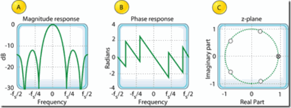
Figure 4: Characteristics of a single-stage CIC filter when D = 5 1阶CIC滤波器的频率响应,Equation 7在单位圆上的z变换: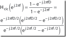
Equation 8
Equation 9 If we ignore the phase factor in Equation 9, that ratio of sin() terms can be approximated by a sin(x )/x function. This means the CIC filter's frequency magnitude response is approximately equal to a sin(x )/x function centered at 0Hz as we see in Figure 4a. (This is why CIC filters are sometimes called sinc filters.) 虽然在单位圆上有极点,但是CIC滤波器的系数都是1,滤波器系数没有量化误差,因此CIC滤波器并不存在通常滤波器因在单位圆上有极点而导致的风险。虽然有递归,但是CIC滤波器是稳定的,线性相位的,有有限长度的脉冲响应。在0Hz处(DC),CIC滤波器增益等于comb滤波器delay D. CIC 滤波器在抽取和插值中的应用
Figure 5: Single-stage CIC filters used in decimation and interpolation 大多数的CIC滤波器的rate change R等于comb的差分延时D.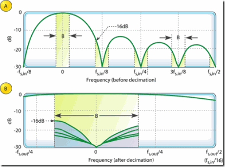
Figure 6: Magnitude response of a 1st-order, D = 8, decimating CIC filter: before decimation; aliasiing after R = 8 decimation ƒs ,out = ƒs ,in /R The spectral band, of width B , centered at 0Hz is the desired passband of the filter. A key aspect of CIC filters is the spectral folding that takes place due to decimation. 假设CIC的输入信号的频谱是在[-ƒs ,in /2, ƒs ,in /2 ]上的方波,那么经过CIC滤波器以后的输出信号的频谱如figure 6a绿 {MOD}的包络所示。 我们知道,在8分之一下采用的情况下,ƒs ,out /2 是下采用后信号的频域边界,即ƒs ,in /16 。下采样后信号频域范围是[-ƒs ,out /2, ƒs ,out /2 ],即是[-ƒs ,in /16, ƒs ,in /16 ],带宽为ƒs ,in /8 。采样前信号在ƒs ,in /8 的整数倍为中心频率,宽度为 ƒs ,in /8 的频谱都会混迭到 下采样后的信号频带内。虽然下采样后信号的ƒs ,in /8 频带都被混迭了,由于我们真正关心的是以0hz为中心,带宽为B的一段频带,在这个频带外的频谱不需要考虑。 Figure 6a 中用阴影表示了将要被混迭且影响目标频带的频谱。 Figure 6b 是对混迭后(下采样后)目标频带的频谱混迭情况。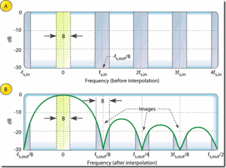
Figure 7: 1st-order, D = R = 8, interpolating CIC filter spectra: input spectrum; output spectral images Figure 7a 是一个任意的基带频谱和它的由于8倍插值而产生的在ƒs ,in 整数倍上的频谱复制。 Figure 7b是滤波器的输出频谱,反映了不完美的滤波引入的不需要的频谱镜像。 在CIC滤波器后连接一个传统的lowpass tapped-delay-line FIR滤波器,如果这个滤波器的阻带包含第一个频谱镜像,那么可以很好的滤除这些频谱镜像。 Improving CIC attenuation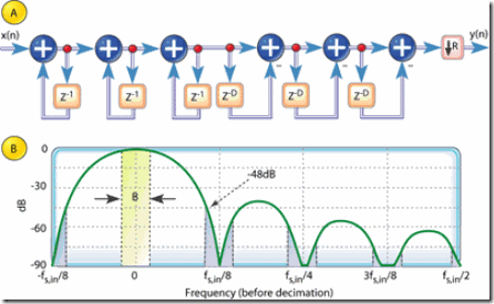
Figure 8: 3rd-order CIC decimation filter structure, and magnitude response before decimation when D = R = 8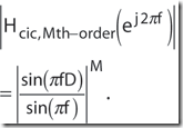
Equation 10 提高抗混迭衰减的代价是增加了硬件加法器的使用,同时还增加了通带的弯曲下垂。 另外,增加滤波器阶数会影响到滤波器增益,滤波器增益跟阶数成指数关系。因为为保持稳定,CIC分不清通常需要全精度,加法器的bit数为M log2 (D ),这意味着高滤波器阶数需要大的数据位宽。即使如此,多级实现形式在商用集成电路中是很常用的,M阶的CIC滤波器常称为sincM 滤波器。 Building a CIC filter
Figure 9: Single-stage CIC filter implementations: for decimation; for interpolation 通常将CIC滤波器的comb部分放在低采样率区域来减少用于存储delay的存储器的size.
Figure 10: CIC decimation filter responses: for various values of differential delay N , when R = 8; for two decimation factors when N =2 那些采样率比高的采样率转换,其comb部分的差分延时的设计参数N的典型值是1或2。N有效的决定了抽取滤波器频率响应中零点的个数。如Figure 10a所示。 CIC抽取滤波器的一个重要特征是:在N一定的情况下,对于不同的抽取率R,滤波器响应的形状变化很小,如图figure 10b所示。当R大于16时,变化可以忽略不计。因此不同抽取率的系统可以用同样的补偿FIR滤波器。 CIC滤波器在每个积分部分有unity feedback,因此它遭受寄存器溢出之扰。不过只有满足下面2个条件,溢出没有影响。 · the range of the number system is greater than or equal to the maximum value expected at the output, and · the filter is implemented with two's complement (nonsaturating) arithmetic. 因为一阶CIC滤波器在0Hz(DC)的增益D = NR , M cascaded CIC decimation filters have a net gain of (NR )M .每一级积分器必须增加NR bits width. 插值CIC滤波器在每2个采样值之间插入零,这降低了增益,因子为1/R , 因此插值CIC滤波器的整体增益为(NR )M /R . 因为必须用整数运算,每一级字宽必须要能够容纳这一级的最大信号(full-scale输入乘以增益)。 虽然 Mth-order CIC decimation filter 得增益是(NR )M ,individual integrators can experience overflow. (Their gain is infinite at DC.) As such, the use of two's complement arithmetic resolves this overflow situation just so long as the integrator word width accommodates the maximum difference between any two successive samples (in other words, the difference causes no more than a single overflow). Using the two's complement binary format, with its modular wrap-around property, the follow-on comb filter will properly compute the correct difference between two successive integrator output samples. 对于插值器,字宽在每一级comb滤波器会增加一个bit,因为积分器具有的累积特性,必须避免溢出。因此,必须在每一级comb滤波器增加一个bit的字宽给插值用。也可以不增加字宽而是丢弃每一级comb滤波器的LSB,这样会增加滤波器输出的noise. Compensation filters 在典型的抽取/插值滤波器应用中,我们需要滤波器具有合理的平坦的通带和窄的过渡带。CIC滤波器自身不能够满足这样的需求,因为它的弯曲的通带增益和宽的过渡带。例如在抽取器中,在CIC滤波器之后级联一个补偿非递归FIR滤波器可以缓解这个问题,如figure 1a所示。
Figure 11: Compensation FIR filter responses; with a 1st-order decimation CIC filter; with a 3rd-order decimation
Figure 11a: 简单的3-tap FIR滤波器 [-1/16, 9/8, -1/16]. 来补偿1st-order R = 8 CIC filter。 Figure 11b:15-tap compensation FIR filter having the coefficients [-1, 4, -16, 32, -64, 136, -352, 1312, -352, 136, -64, 32, -16, 4, -1]来补偿 3rd-order R = 8 CIC filter. Those dashed curves in Figure 11 represent the frequency magnitude responses of compensating FIR filters within which no sample-rate change takes place. (The FIR filters' input and output sample rates are equal to the ƒs ,out output rate of the decimating CIC filter.) If a compensating FIR filter were designed to provide an additional decimation by two, its frequency magnitude response would look similar to that in Figure 12, where >s ,in is the compensation filter's input sample rate.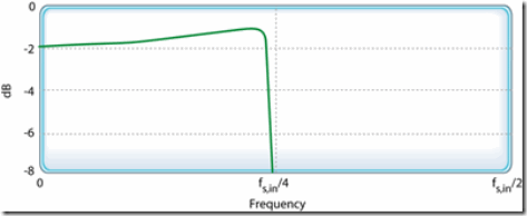
Figure 12: Frequency magnitude response of a decimate-by-2 compensation FIR filter
Advanced techniques 抽取CIC滤波器只不过是滑动平均滤波器的一个非常高效的迭代实现,有NR taps, 其输出再进行 R 抽取 . 同样,插值CIC滤波器在每两个输入采样之间插入R -1个0,然后通过一个NR -tap的工作在输出采样率ƒs ,out 的滑动平均滤波器。对于高采样率转换率的抽取和插值来说,Figure 1所示的级联形式的计算量大大低于单一FIR滤波器的计算量。 下图与figure 9a相同,下面是下图中两种方式的matlab实现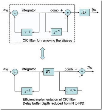 % For decimation, having the CIC filtering before taking every other sample
D = 2; % decimation factor
N = 10; % delay buffer depth
delayBuffer = zeros(1,N); % init
intOut = 0;
xn = sin(2*pi*[0:.1:10]);
y6n = [];
for ii = 1:length(xn)
% comb section
combOut = xn(ii) – delayBuffer(end);
delayBuffer(2:end) = delayBuffer(1:end-1);
delayBuffer(1) = xn(ii); % integrator
intOut = intOut + combOut;
y6n = [y6n intOut]; end
y6n = y6n(1:D:end); % taking every other sample – decimation % For efficient hardware implementation of the CIC filter, having the
% integrator section first, decimate, then the comb stage
% Gain : Reduced the delay buffer depth of comb section from N to N/D
D = 2; % decimation factor
N = 10; % delay buffer depth
delayBuffer = zeros(1,N/D);
intOut = 0;
xn = sin(2*pi*[0:.1:10]); % input
y7n = []; % output
for ii = 1:length(xn)
% integrator
intOut = intOut + xn(ii); if mod(ii,2)==1
% comb section
combOut = intOut – delayBuffer(end);
delayBuffer(2:end) = delayBuffer(1:end-1);
delayBuffer(1) = intOut;
y7n = [ y7n combOut];
end end
err67 = y6n – y7n;
err67dB = 10*log10(err67*err67′/length(err67)) 下图跟figure 9b相同,下面是下图2中形式的matlab实现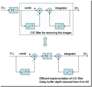 % For interpolation, insert the zeros followed by CIC filtering
xn = sin(2*pi*[0:.1:10]);
I = 2; % interpolation factor
N = 10; % filter buffer depth
xUn = [xn; zeros(1,length(xn))];
xUn = xUn(:).’; % zeros inserted
delayBuffer = zeros(1,N);
intOut = 0;
for ii = 1:length(xUn)
% comb section
combOut = xUn(ii) – delayBuffer(end);
delayBuffer(2:end) = delayBuffer(1:end-1);
delayBuffer(1) = xUn(ii); % integrator
intOut = intOut + combOut;
y4n(ii) = intOut; end % For efficient hardware implementation of CIC filter for interpolation, having
% the comb section, then zeros insertion, followed by integrator section
% Gain : Reduced the delay buffer depth of comb section from N to N/I I = 2; % interpolation factor
N = 10; % original delay buffer depth
delayBuffer = zeros(1,N/I); % new delay buffer of N/I
intOut = 0;
xn = sin(2*pi*[0:.1:10]);
y5n = [];
for ii = 1:length(xn)
% comb section
combOut = xn(ii) – delayBuffer(end);
delayBuffer(2:end) = delayBuffer(1:end-1);
delayBuffer(1) = xn(ii); % upsampling
combOutU = [ combOut zeros(1,1)]; for jj =0:I-1
% integrator
intOut = intOut + combOutU(jj+1);
y5n = [y5n intOut];
end end err45 = y4n – y5n;
err45dB = 10*log10(err45*err45′/length(err45)) % outputs matching
 Figure 1: CIC filter applications
因为CIC滤波器的幅频响应包络象sin(x)/x,通常在CIC滤波器之前或者之后都有一个high-performance linear-phase lowpass tapped-delay-line FIR filters, 用于补偿CIC滤波器不够平坦的通带。
CIC滤波器不需要乘法运算,易于硬件实现。
抽取CIC滤波器只不过是滑动平均滤波器的一个非常高效的迭代实现,有NR
taps, 其输出再进行 R
抽取
. 同样,插值CIC滤波器在每两个输入采样之间插入R
-1个0,然后通过一个NR
-tap的工作在输出采样率ƒs
,out
的滑动平均滤波器。对于高采样率转换率的抽取和插值来说,Figure 1所示的级联形式的计算量大大低于单一FIR滤波器的计算量。
Recursive running-sum filter

Figure 2: D-point averaging filters Figure 2a是标准的D-point moving-average 处理,需要D-1次加法运算和1次乘法运算。时域表达式:

Equation 1 z域表达式:

Equation 2 z域传递函数:

Equation 3 Figure 2b: 迭代running-sum filter,等价于figure 2a. y(n) = 1/D * [x(n) + x(n-1) + … + x(n-D+1)] y(n-1) = 1/D * [x(n-1) + x(n-2) + x(n-D+1) + x(n-D)] y(n) – y(n-1) = 1/D * [x(n) – x(n-D)]

Equation 4 z域传递函数:

Equation 5 Equation 3 和 Equation 5 本质是一样的。Equation 3 是非递归表达式,equation 5是递归表达式。不考虑delay length D的话,递归形式只需要一个加法和一个减法运算。 例子:figure 1a的matlab实现,滑动平均滤波器,忽略scale factor % Moving Average filter
N = 10; %延时
xn = sin(2*pi*[0:.1:10]); %n=[0:1:100]; sin(2*pi*f*t)=sin(2*pi*f*T*n)=>f=1Hz, fs=10Hz.
hn = ones(1,N); %脉冲响应
y1n = conv(xn,hn); % transfer function of Moving Average filter
hF = fft(hn,1024);
plot([-512:511]/1024, abs(fftshift(hF)));
xlabel(’Normalized frequency’)
ylabel(’Amplitude’)
title(’frequency response of Moving average filter’)
 Figure 1c的matlab实现
% Implementing Cascaded Integrator Comb filter with the
 % comb section following the integrator stage
N = 10;
delayBuffer = zeros(1,N);
intOut = 0;
xn = sin(2*pi*[0:.1:10]);
for ii = 1:length(xn)
% comb section
combOut = xn(ii) – delayBuffer(end);
delayBuffer(2:end) = delayBuffer(1:end-1);
delayBuffer(1) = xn(ii); % integrator
intOut = intOut + combOut;
y2n(ii) = intOut;
end err12 = y1n(1:length(xn)) – y2n;
err12dB = 10*log10(err12*err12′/length(err12)) % identical outputs
close all
 先integrator后comb的实现
% Implementing Cascaded Integrator Comb filter with the
 % integrator section following the comb stage N = 10;
delayBuffer = zeros(1,N);
intOut = 0;
xn = sin(2*pi*[0:.1:10]);
for ii = 1:length(xn)
% integrator
intOut = intOut + xn(ii); % comb section
combOut = intOut – delayBuffer(end);
delayBuffer(2:end) = delayBuffer(1:end-1);
delayBuffer(1) = intOut;
y3n(ii) = combOut; end
err13 = y1n(1:length(xn)) – y3n;
err13dB = 10*log10(err13*err13′/length(err13)) % identical outputs CIC filter structures Figure 2c: the classic form of 1st-order CIC filter, 忽略figure 2b中的1/D因子。 其中前馈部分称为comb section, 其differential delay 是D;反馈部分称为积分器。 差分方程:
Equation 6

Equation 7

Figure 3: Single-stage CIC filter time-domain responses when D = 5 Figure 2c这个1阶CIC滤波器看做是2部分的级联。Figure 3a是comb stage的脉冲响应,figure 3b是积分器的脉冲响应,figure 3c是整个系统的脉冲响应。系统的脉冲响应是一个矩形序列,等价于moving-average filter和recursive running-sum filter的单位脉冲响应,仅仅相差一个常数的scale factor。

Figure 4: Characteristics of a single-stage CIC filter when D = 5 1阶CIC滤波器的频率响应,Equation 7在单位圆上的z变换:

Equation 8

Equation 9 If we ignore the phase factor in Equation 9, that ratio of sin() terms can be approximated by a sin(x )/x function. This means the CIC filter's frequency magnitude response is approximately equal to a sin(x )/x function centered at 0Hz as we see in Figure 4a. (This is why CIC filters are sometimes called sinc filters.) 虽然在单位圆上有极点,但是CIC滤波器的系数都是1,滤波器系数没有量化误差,因此CIC滤波器并不存在通常滤波器因在单位圆上有极点而导致的风险。虽然有递归,但是CIC滤波器是稳定的,线性相位的,有有限长度的脉冲响应。在0Hz处(DC),CIC滤波器增益等于comb滤波器delay D. CIC 滤波器在抽取和插值中的应用

Figure 5: Single-stage CIC filters used in decimation and interpolation 大多数的CIC滤波器的rate change R等于comb的差分延时D.

Figure 6: Magnitude response of a 1st-order, D = 8, decimating CIC filter: before decimation; aliasiing after R = 8 decimation ƒs ,out = ƒs ,in /R The spectral band, of width B , centered at 0Hz is the desired passband of the filter. A key aspect of CIC filters is the spectral folding that takes place due to decimation. 假设CIC的输入信号的频谱是在[-ƒs ,in /2, ƒs ,in /2 ]上的方波,那么经过CIC滤波器以后的输出信号的频谱如figure 6a绿 {MOD}的包络所示。 我们知道,在8分之一下采用的情况下,ƒs ,out /2 是下采用后信号的频域边界,即ƒs ,in /16 。下采样后信号频域范围是[-ƒs ,out /2, ƒs ,out /2 ],即是[-ƒs ,in /16, ƒs ,in /16 ],带宽为ƒs ,in /8 。采样前信号在ƒs ,in /8 的整数倍为中心频率,宽度为 ƒs ,in /8 的频谱都会混迭到 下采样后的信号频带内。虽然下采样后信号的ƒs ,in /8 频带都被混迭了,由于我们真正关心的是以0hz为中心,带宽为B的一段频带,在这个频带外的频谱不需要考虑。 Figure 6a 中用阴影表示了将要被混迭且影响目标频带的频谱。 Figure 6b 是对混迭后(下采样后)目标频带的频谱混迭情况。

Figure 7: 1st-order, D = R = 8, interpolating CIC filter spectra: input spectrum; output spectral images Figure 7a 是一个任意的基带频谱和它的由于8倍插值而产生的在ƒs ,in 整数倍上的频谱复制。 Figure 7b是滤波器的输出频谱,反映了不完美的滤波引入的不需要的频谱镜像。 在CIC滤波器后连接一个传统的lowpass tapped-delay-line FIR滤波器,如果这个滤波器的阻带包含第一个频谱镜像,那么可以很好的滤除这些频谱镜像。 Improving CIC attenuation

Figure 8: 3rd-order CIC decimation filter structure, and magnitude response before decimation when D = R = 8

Equation 10 提高抗混迭衰减的代价是增加了硬件加法器的使用,同时还增加了通带的弯曲下垂。 另外,增加滤波器阶数会影响到滤波器增益,滤波器增益跟阶数成指数关系。因为为保持稳定,CIC分不清通常需要全精度,加法器的bit数为M log2 (D ),这意味着高滤波器阶数需要大的数据位宽。即使如此,多级实现形式在商用集成电路中是很常用的,M阶的CIC滤波器常称为sincM 滤波器。 Building a CIC filter

Figure 9: Single-stage CIC filter implementations: for decimation; for interpolation 通常将CIC滤波器的comb部分放在低采样率区域来减少用于存储delay的存储器的size.

Figure 10: CIC decimation filter responses: for various values of differential delay N , when R = 8; for two decimation factors when N =2 那些采样率比高的采样率转换,其comb部分的差分延时的设计参数N的典型值是1或2。N有效的决定了抽取滤波器频率响应中零点的个数。如Figure 10a所示。 CIC抽取滤波器的一个重要特征是:在N一定的情况下,对于不同的抽取率R,滤波器响应的形状变化很小,如图figure 10b所示。当R大于16时,变化可以忽略不计。因此不同抽取率的系统可以用同样的补偿FIR滤波器。 CIC滤波器在每个积分部分有unity feedback,因此它遭受寄存器溢出之扰。不过只有满足下面2个条件,溢出没有影响。 · the range of the number system is greater than or equal to the maximum value expected at the output, and · the filter is implemented with two's complement (nonsaturating) arithmetic. 因为一阶CIC滤波器在0Hz(DC)的增益D = NR , M cascaded CIC decimation filters have a net gain of (NR )M .每一级积分器必须增加NR bits width. 插值CIC滤波器在每2个采样值之间插入零,这降低了增益,因子为1/R , 因此插值CIC滤波器的整体增益为(NR )M /R . 因为必须用整数运算,每一级字宽必须要能够容纳这一级的最大信号(full-scale输入乘以增益)。 虽然 Mth-order CIC decimation filter 得增益是(NR )M ,individual integrators can experience overflow. (Their gain is infinite at DC.) As such, the use of two's complement arithmetic resolves this overflow situation just so long as the integrator word width accommodates the maximum difference between any two successive samples (in other words, the difference causes no more than a single overflow). Using the two's complement binary format, with its modular wrap-around property, the follow-on comb filter will properly compute the correct difference between two successive integrator output samples. 对于插值器,字宽在每一级comb滤波器会增加一个bit,因为积分器具有的累积特性,必须避免溢出。因此,必须在每一级comb滤波器增加一个bit的字宽给插值用。也可以不增加字宽而是丢弃每一级comb滤波器的LSB,这样会增加滤波器输出的noise. Compensation filters 在典型的抽取/插值滤波器应用中,我们需要滤波器具有合理的平坦的通带和窄的过渡带。CIC滤波器自身不能够满足这样的需求,因为它的弯曲的通带增益和宽的过渡带。例如在抽取器中,在CIC滤波器之后级联一个补偿非递归FIR滤波器可以缓解这个问题,如figure 1a所示。

Figure 11: Compensation FIR filter responses; with a 1st-order decimation CIC filter; with a 3rd-order decimation
Figure 11a: 简单的3-tap FIR滤波器 [-1/16, 9/8, -1/16]. 来补偿1st-order R = 8 CIC filter。 Figure 11b:15-tap compensation FIR filter having the coefficients [-1, 4, -16, 32, -64, 136, -352, 1312, -352, 136, -64, 32, -16, 4, -1]来补偿 3rd-order R = 8 CIC filter. Those dashed curves in Figure 11 represent the frequency magnitude responses of compensating FIR filters within which no sample-rate change takes place. (The FIR filters' input and output sample rates are equal to the ƒs ,out output rate of the decimating CIC filter.) If a compensating FIR filter were designed to provide an additional decimation by two, its frequency magnitude response would look similar to that in Figure 12, where >s ,in is the compensation filter's input sample rate.

Figure 12: Frequency magnitude response of a decimate-by-2 compensation FIR filter
Advanced techniques 抽取CIC滤波器只不过是滑动平均滤波器的一个非常高效的迭代实现,有NR taps, 其输出再进行 R 抽取 . 同样,插值CIC滤波器在每两个输入采样之间插入R -1个0,然后通过一个NR -tap的工作在输出采样率ƒs ,out 的滑动平均滤波器。对于高采样率转换率的抽取和插值来说,Figure 1所示的级联形式的计算量大大低于单一FIR滤波器的计算量。 下图与figure 9a相同,下面是下图中两种方式的matlab实现
 % For decimation, having the CIC filtering before taking every other sample
 D = 2; % decimation factor
N = 10; % delay buffer depth
delayBuffer = zeros(1,N); % init
intOut = 0;
xn = sin(2*pi*[0:.1:10]);
y6n = [];
for ii = 1:length(xn)
% comb section
combOut = xn(ii) – delayBuffer(end);
delayBuffer(2:end) = delayBuffer(1:end-1);
delayBuffer(1) = xn(ii); % integrator
intOut = intOut + combOut;
y6n = [y6n intOut]; end
y6n = y6n(1:D:end); % taking every other sample – decimation % For efficient hardware implementation of the CIC filter, having the
% integrator section first, decimate, then the comb stage
% Gain : Reduced the delay buffer depth of comb section from N to N/D
D = 2; % decimation factor
N = 10; % delay buffer depth
delayBuffer = zeros(1,N/D);
intOut = 0;
xn = sin(2*pi*[0:.1:10]); % input
y7n = []; % output
for ii = 1:length(xn)
% integrator
intOut = intOut + xn(ii); if mod(ii,2)==1
% comb section
combOut = intOut – delayBuffer(end);
delayBuffer(2:end) = delayBuffer(1:end-1);
delayBuffer(1) = intOut;
y7n = [ y7n combOut];
end end
err67 = y6n – y7n;
err67dB = 10*log10(err67*err67′/length(err67)) 下图跟figure 9b相同,下面是下图2中形式的matlab实现
 % For interpolation, insert the zeros followed by CIC filtering
 xn = sin(2*pi*[0:.1:10]);
I = 2; % interpolation factor
N = 10; % filter buffer depth
xUn = [xn; zeros(1,length(xn))];
xUn = xUn(:).’; % zeros inserted
delayBuffer = zeros(1,N);
intOut = 0;
for ii = 1:length(xUn)
% comb section
combOut = xUn(ii) – delayBuffer(end);
delayBuffer(2:end) = delayBuffer(1:end-1);
delayBuffer(1) = xUn(ii); % integrator
intOut = intOut + combOut;
y4n(ii) = intOut; end % For efficient hardware implementation of CIC filter for interpolation, having
% the comb section, then zeros insertion, followed by integrator section
% Gain : Reduced the delay buffer depth of comb section from N to N/I I = 2; % interpolation factor
N = 10; % original delay buffer depth
delayBuffer = zeros(1,N/I); % new delay buffer of N/I
intOut = 0;
xn = sin(2*pi*[0:.1:10]);
y5n = [];
for ii = 1:length(xn)
% comb section
combOut = xn(ii) – delayBuffer(end);
delayBuffer(2:end) = delayBuffer(1:end-1);
delayBuffer(1) = xn(ii); % upsampling
combOutU = [ combOut zeros(1,1)]; for jj =0:I-1
% integrator
intOut = intOut + combOutU(jj+1);
y5n = [y5n intOut];
end end err45 = y4n – y5n;
err45dB = 10*log10(err45*err45′/length(err45)) % outputs matching