对于TI C66x DSP的每个CPU有INT4~15共12个中断输入。对于中断,event combiner将INTC的输入event 4~127分为4个组(event 0~3为INTC内部使用,如图示为event combiner的四个输出),然后event 0~127作为Interrupt Selector的输入。类似于4.x中的exception,中断也有同样功能的event flag,event mask,masked event flag寄存器。
event combiner
The basic concept of the event combiner is to perform an OR operation on a subset of the system event flags (described inTable
9-2). The results of the OR operation areprovided as a new “combined” event).The event combiner divides the 124 system events (4~127)into
four groups. The first group includes events 4 through 31, the second group includes events 32 through 63, the third group includes events 64 through 95, and the fourth group includes events 96 through 127. You can combine events within each group to provide
a new “combined” event. These new events are designated EVT0, EVT1, EVT2, and EVT3. These events are routed to the interrupt selector along with the original 124 system events for a combined total of 128 events. For each group there is an event mask register.
The content of the masked event flag registers is identical to the content of the event flag registers for the events that are enabled in the event mask registers. By reading the masked event flag registers, the
DSP only sees the event flags pertaining to the corresponding combined event (EVT [3:0]), which can be useful in interrupt routines servicing combined events.
Interrupt Seclctor(exception没有类似模块,见下图):
The DSP has twelve maskable interrupts (DSPINT4 through 15) are available. The interrupt selector allows any of the 128 system events to route to any of the twelve DSP interrupt inputs.
The 128 system events are either event inputs or event combinations generated by the event combiner. The event combiner logic has the capability of grouping multiple event inputs to four possible event outputs. These
outputs are then provided to the interrupt selector and treated as additional system events (EVT0 through EVT3).
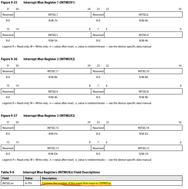
The interrupt selector contains interrupt multiplexing registers, INTMUX[3:1] that allow you to program the source for each of the 12 available DSP interrupts. Each of the events that are presented to the interrupt selector has
an event number that is used to program these registers.The order of the DSP interrupts (DSPINT4 through DSPINT15) determines the priority for pending interrupts. Since any interrupt service routine can be atomic (not nestable), the DSP interrupt priority
only applies to pending interrupts.
Interrupt Mux Registers (INTMUXn,见文中的图) : The interrupt selector contains interrupt mux registers that allow you to program the source for each
of the 12 available DSP interrupts.
Example, assuming the following configuration:
EVTFLAG3 =
01101010010011001110001110010101
EVTMASK3 = 00001111111111111111111111111111
The Masked Event Flag register 3 will be:
MEVTFLAG3 = 01100000000000000000000000000000 When servicing a combined interrupt, you must:
1. Read the MEVTFLAGx register corresponding to the combined event EVTx
2. Check for the first pending (i.e., flagged) events
3. Write this MEVTFLAGx value to the EVTCLRx register(清除MEVTFLAGx寄存器相应位)
4. Service the event indicated in step 2
5. Repeat steps 1 through 4 until the MEVTFLAGx register = 0
This procedure only evaluates and clears those events combined on EVTx. Further, any events that are masked in the EVTMASKx register are not be cleared (and they do not need to clear), even if they are set in the EVTFLAGx register (this allows you to use them to generate an exception,中断没有使用的event,exception可以使用). Note—The DSP should iterate steps 1 to 4 until no pending events are foundbefore returning within the interrupt service routine. This ensures that any events that are received during the interrupt service routine are captured (also remember that if an event EVTx is received at the same time that its flag is cleared in the EVTCLRy [x] register, then it will not clear). Register(IFR,ICR,IER etc): Interrupt Clear Register (ICR)
Interrupt Enable Register (IER)
Interrupt Flag Register (IFR)
Interrupt Return Pointer Register (IRP)
Interrupt Set Register (ISR)
Interrupt Service Table Pointer Register (ISTP)
Nonmaskable Interrupt (NMI) Return Pointer Register (NRP)
For these regster, please refer to "TMS320C66x_DSP_CPU_and_Instruction and Set.pdf".

 Interrupt Mux Register:

EVTMASK3 = 00001111111111111111111111111111
The Masked Event Flag register 3 will be:
MEVTFLAG3 = 01100000000000000000000000000000 When servicing a combined interrupt, you must:
1. Read the MEVTFLAGx register corresponding to the combined event EVTx
2. Check for the first pending (i.e., flagged) events
3. Write this MEVTFLAGx value to the EVTCLRx register(清除MEVTFLAGx寄存器相应位)
4. Service the event indicated in step 2
5. Repeat steps 1 through 4 until the MEVTFLAGx register = 0
This procedure only evaluates and clears those events combined on EVTx. Further, any events that are masked in the EVTMASKx register are not be cleared (and they do not need to clear), even if they are set in the EVTFLAGx register (this allows you to use them to generate an exception,中断没有使用的event,exception可以使用). Note—The DSP should iterate steps 1 to 4 until no pending events are foundbefore returning within the interrupt service routine. This ensures that any events that are received during the interrupt service routine are captured (also remember that if an event EVTx is received at the same time that its flag is cleared in the EVTCLRy [x] register, then it will not clear). Register(IFR,ICR,IER etc): Interrupt Clear Register (ICR)
Interrupt Enable Register (IER)
Interrupt Flag Register (IFR)
Interrupt Return Pointer Register (IRP)
Interrupt Set Register (ISR)
Interrupt Service Table Pointer Register (ISTP)
Nonmaskable Interrupt (NMI) Return Pointer Register (NRP)
For these regster, please refer to "TMS320C66x_DSP_CPU_and_Instruction and Set.pdf".


 Interrupt Mux Register:
