{var%20f='http://v.t.sina.com.cn/share/share.php?appkey=1515056452',u=z||d.location,p=['&url=',e(u),'&title=',e(t||d.title),'&source=',e(r),'&sourceUrl=',e(l),'&content=',c||'gb2312','&pic=',e(p||'')].join('');function%20a(){if(!window.open([f,p].join(''),'mb',['toolbar=0,status=0,resizable=1,width=440,height=430,left=',(s.width-440)/2,',top=',(s.height-430)/2].join('')))u.href=[f,p].join('');};if(/Firefox/.test(navigator.userAgent))setTimeout(a,0);else%20a();})(screen,document,encodeURIComponent,'','','https://www.xiaopingtou.cn//data/attach/topic/topicKPo7gB.jpg', '推荐 Ginbo 的文章《CCS5.4+Proteus8的F28027实践课三、外部中断0控制LED流水灯》','https://www.xiaopingtou.net/article-83965.html','页面编码gb2312|utf-8默认gb2312'));)
吃完回来了,跟老弟打了个电话,他正处于事业的迷茫期,希望他早点走出这个状态。好了,现在已经晚上八点过十分了,希望十点前能把外部中断这个主题讲完。
外部中断的概念我还是稍微说下吧,就是你映射的外部中断引脚,如果检测到相应的脉冲边沿变化,就进入外部中断处理程序,处理完后跳出中断,等待下次边沿跳变。
现在来回顾下我们外部中断的结构图:
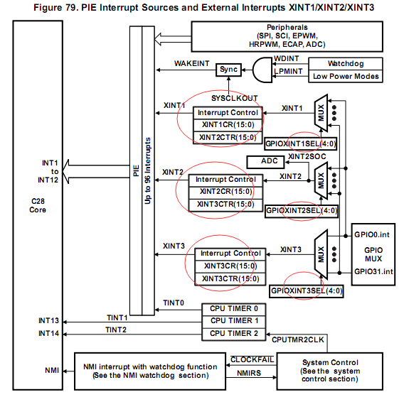
看到这张图,大家有没有一种直接写程序的冲动,呵呵,这说明大家都前面中断那章节学习的还不错,对寄存器的操作也已经有了自己的理解。
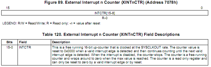
但外部中断寄存器这部分还是需要回顾下:

寄存器这里大家也再次明白了,其实现在也差不多可以写程序了,不过还是要回顾下外部中断的PIE映射表:
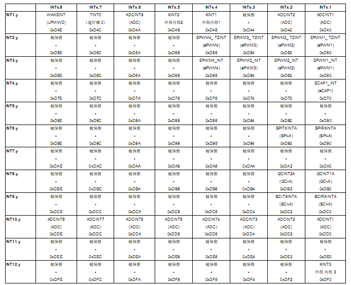
我们这次要使用的是外部中断1,也就是INT1.4
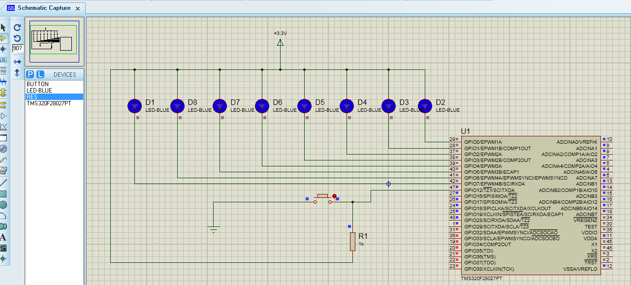
来来来,开始写程序,从最简单的GPIO.c文件开始,因为我们本次课程新增了一个外部中断输入触发端口,我选择了GPIO12,因为这个端口离LED最近,好画图。。
GPIO的操作流程我再复述一遍:
1、引脚规划;
2、通过复用寄存器设置相应引脚的功能;
3、输入滤波设置;
4、数字GPIO引脚方向设置;
5、内部上拉电阻使能或禁止;
好了,直接上程序了
刚才采样时钟那里花了我一些时间,本来我取的是最大值510 * SYSCLKOUT,但是仿真一直没反应,我还以为是其他地方有问题,可其他地方检查两边都没发现明显问题,那我想肯定是采样时钟这里,毕竟我是在Protues里面仿真的,系统运行的时间看的到是以ms为单位,所以如果把采样时间设的过大,会导致采样时间内没捕捉到跳变,这个问题应该只是仿真需要注意,到时候做成品板的时候,我觉得还是要设为最大值。
好了,现在时间刚好九点半,离我们的预期时间早了半个小时,不错,先设定目标,再突破目标,是每个狼性文化的标准,那我们现在趁热打铁,去驱动12864。
菜鸟交流qq群107691092
外部中断的概念我还是稍微说下吧,就是你映射的外部中断引脚,如果检测到相应的脉冲边沿变化,就进入外部中断处理程序,处理完后跳出中断,等待下次边沿跳变。
现在来回顾下我们外部中断的结构图:
看到这张图,大家有没有一种直接写程序的冲动,呵呵,这说明大家都前面中断那章节学习的还不错,对寄存器的操作也已经有了自己的理解。
但外部中断寄存器这部分还是需要回顾下:
寄存器这里大家也再次明白了,其实现在也差不多可以写程序了,不过还是要回顾下外部中断的PIE映射表:
我们这次要使用的是外部中断1,也就是INT1.4
来来来,开始写程序,从最简单的GPIO.c文件开始,因为我们本次课程新增了一个外部中断输入触发端口,我选择了GPIO12,因为这个端口离LED最近,好画图。。
GPIO的操作流程我再复述一遍:
1、引脚规划;
2、通过复用寄存器设置相应引脚的功能;
3、输入滤波设置;
4、数字GPIO引脚方向设置;
5、内部上拉电阻使能或禁止;
好了,直接上程序了
void InitGpio(void)
{
   EALLOW;

   // Each GPIO pin can be:
   // a) a GPIO input/output
   // b) peripheral function 1
   // c) peripheral function 2
   // d) peripheral function 3
   // By default, all are GPIO Inputs
   GpioCtrlRegs.GPAMUX1.all = 0x0000;     // GPIO functionality GPIO0-GPIO15
   GpioCtrlRegs.GPAMUX2.all = 0x0000;     // GPIO functionality GPIO16-GPIO31
   GpioCtrlRegs.GPBMUX1.all = 0x0000;     // GPIO functionality GPIO32-GPIO34
   GpioCtrlRegs.AIOMUX1.all = 0x0000;     // Dig.IO funct. applies to AIO2,4,6,10,12,14

   GpioCtrlRegs.GPADIR.all = 0xFFFFFFFF;      // GPIO0-GPIO31 are GP outputs
   GpioCtrlRegs.GPBDIR.all = 0x0000;      // GPIO32-GPIO34 are inputs
   GpioCtrlRegs.AIODIR.all = 0x0000;      // AIO2,4,6,19,12,14 are digital inputs

   GpioCtrlRegs.GPADIR.bit.GPIO12=0;      //GPIO12 is input pin

   // Each input can have different qualification
   // a) input synchronized to SYSCLKOUT
   // b) input qualified by a sampling window
   // c) input sent asynchronously (valid for peripheral inputs only)
   GpioCtrlRegs.GPAQSEL1.all = 0x0000;    // GPIO0-GPIO15 Synch to SYSCLKOUT
   GpioCtrlRegs.GPAQSEL2.all = 0x0000;    // GPIO16-GPIO31 Synch to SYSCLKOUT
   GpioCtrlRegs.GPBQSEL1.all = 0x0000;    // GPIO32-GPIO34 Synch to SYSCLKOUT

   GpioCtrlRegs.GPAQSEL1.bit.GPIO12=2;    // six samples
   GpioCtrlRegs.GPACTRL.bit.QUALPRD1=0x0f // 14 * SYSCLKOUT

   // Pull-ups can be enabled or disabled.
   GpioCtrlRegs.GPAPUD.all = 0x0000;      // Pullup's enabled GPIO0-GPIO31
   GpioCtrlRegs.GPBPUD.all = 0x0000;      // Pullup's enabled GPIO32-GPIO34
   //GpioCtrlRegs.GPAPUD.all = 0xFFFF;    // Pullup's disabled GPIO0-GPIO31
   //GpioCtrlRegs.GPBPUD.all = 0xFFFF;    // Pullup's disabled GPIO32-GPIO34

   GpioCtrlRegs.GPAPUD.bit.GPIO12=1;      // Pullup's disabled GPIO12

   GpioIntRegs.GPIOXINT1SEL.bit.GPIOSEL=12; // GPIO12 is the XINT1's source

   EDIS;
}
写完GPIO.c文件,现在要写外部中断程序,中断函数直接去TI提供的F2802x_DefaultIsr.c文件修改就行了,修改后如下:
interrupt void  XINT1_ISR(void)
{
  // Insert ISR Code here
    GpioDataRegs.GPATOGGLE.all=0x000000ff;
  // To receive more interrupts from this PIE group, acknowledge this interrupt
   PieCtrlRegs.PIEACK.all = PIEACK_GROUP1;

  // Next two lines for debug only to halt the processor here
  // Remove after inserting ISR Code
//  asm ("      ESTOP0");
//  for(;;);

}
现在就剩最后一个主函数了,大家要记得,我们外部函数相关的开关都没开,我准备都放在主函数这里,我已经迫不及待了,马上去写出来给大家
void main(void)
{

// Step 1. Initialize System Control:
// PLL, WatchDog, enable Peripheral Clocks
// This example function is found in the DSP2802x_SysCtrl.c file.
   InitSysCtrl();

// Step 2. Initalize GPIO:
// This example function is found in the DSP2802x_Gpio.c file and
// illustrates how to set the GPIO to it's default state.
   InitGpio();

// Step 3. Clear all interrupts and initialize PIE vector table:
// Disable CPU interrupts
   DINT;

// Initialize PIE control registers to their default state.
// The default state is all PIE interrupts disabled and flags
// are cleared.
// This function is found in the DSP2802x_PieCtrl.c file.
   InitPieCtrl();

// Disable CPU interrupts and clear all CPU interrupt flags:
   IER = 0x0000;
   IFR = 0x0000;

// Initialize the PIE vector table with pointers to the shell Interrupt
// Service Routines (ISR).
// This will populate the entire table, even if the interrupt
// is not used in this example.  This is useful for debug purposes.
// The shell ISR routines are found in DSP2802x_DefaultIsr.c.
// This function is found in DSP2802x_PieVect.c.
   InitPieVectTable();


// Step 4. Initialize all the Device Peripherals:
// This function is found in DSP2802x_InitPeripherals.c
// InitPeripherals(); // Not required for this example

// Step 5. User specific code:

   GpioDataRegs.GPADAT.all = 0x00000000;  //GPIO0-GPIO31 initial value are 0

   EALLOW;
   XIntruptRegs.XINT1CR.bit.POLARITY=0;
   XIntruptRegs.XINT1CR.bit.ENABLE=1;

   PieCtrlRegs.PIEIER1.bit.INTx4 = 1;
   PieCtrlRegs.PIECTRL.bit.ENPIE = 1;
   IER = 0x0001;
   EINT;
   EDIS;

   while(1)
   {
//     GpioDataRegs.GPATOGGLE.all=0x000000ff;
//       DELAY_US(1000);
   }
}
总算把主程序调完贴出来了,效果图如下: 刚才采样时钟那里花了我一些时间,本来我取的是最大值510 * SYSCLKOUT,但是仿真一直没反应,我还以为是其他地方有问题,可其他地方检查两边都没发现明显问题,那我想肯定是采样时钟这里,毕竟我是在Protues里面仿真的,系统运行的时间看的到是以ms为单位,所以如果把采样时间设的过大,会导致采样时间内没捕捉到跳变,这个问题应该只是仿真需要注意,到时候做成品板的时候,我觉得还是要设为最大值。
好了,现在时间刚好九点半,离我们的预期时间早了半个小时,不错,先设定目标,再突破目标,是每个狼性文化的标准,那我们现在趁热打铁,去驱动12864。
菜鸟交流qq群107691092