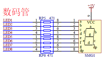
一、项目配置1、新建项目文件夹"TimSeg";2、通过Keil5创建新项目,保存在所创建的文件夹中(设项目名为pTimSeg),选择MCU芯片为"STM32F103ZE"(本程序使用的硬件为:STM32-PZ6806L开发板)3、在"TimSeg"文件夹下新建"CMSIS"、"Device"、"Public"、"Startup"、"User"和"Lib"文件夹。① 在"CMSIS"文件夹中复制"core_cm3.h"和"core_cm3.c"文件;② 在" Device "文件夹中复制"stm32f10x.h"、"system_stm32f10x.h"和"system_stm32f10x.c"文件;③ 在" Startup "文件夹中复制"startup_stm32f10x_hd.s"文件;④在"Lib"文件夹中新建"inc"和"src"两个子文件夹,在"inc"文件夹中复制"misc.h"、"stm32f10x_gpio.h"、"stm32f10x_tim.h"和"stm32f10x_rcc.h"文件;在"src"文件夹中复制"misc.c"、"stm32f10x_gpio.c"、"stm32f10x_tim.c"和"stm32f10x_rcc.c"文件;4、为项目添加"CMSIS"、"Device"、"Public"、"Startup"、"User"和"Lib"组,并将上述C程序文件和"startup_stm32f10x_hd.s"启动文件加入到相应组中。5、打开“项目配置”对话框,在"Output"选项卡中选择"Create HEX File",在"C/C++"选项卡中的"Include Paths"中添加如下包含路径:".CMSIS;", ".Device;", ".Libinc;",".Public;"。6、在"stm32f10x.h"中添加函数参数检查宏(参看:https://blog.csdn.net/fanxp66/article/details/80215090)#ifdef USE_FULL_ASSERT /** * @brief 这个assert_param宏用于函数参数检查 * @param expr:如果expr是 false,就调用 assert_failed函数报告源文件名和 * 失败的行号,如果expr是 true ,就返回一个空值 * @retval None */ #define assert_param(expr) ((expr) ? (void)0 : assert_failed((uint8_t *)__FILE__, __LINE__)) /* Exported functions ------------------------------------------------------- */ void assert_failed(uint8_t* file, uint32_t line); #else #define assert_param(expr) ((void)0) #endif /* USE_FULL_ASSERT */ 7、新建一个文件(system.h),保存到"Public"文件夹中,内容为:#ifndef __SYSTEM__H #define __SYSTEM__H #include "stm32f10x.h" //定义位带地址宏 #define BITBAND(addr,bitnum) ((addr&0xF0000000) + 0x02000000 + ((addr&0x000FFFFF)<<5) + (bitnum<<2)) #define MEM_ADDR(addr) *((volatile unsigned long *)(addr)) #define BIT_ADDR(addr,bitnum) MEM_ADDR(BITBAND(addr,bitnum)) //IO口地址映射 //数据输出寄存器地址 #define GPIOA_ODR_Addr (GPIOA_BASE + 12) #define GPIOB_ODR_Addr (GPIOB_BASE + 12) #define GPIOC_ODR_Addr (GPIOC_BASE + 12) #define GPIOD_ODR_Addr (GPIOD_BASE + 12) #define GPIOE_ODR_Addr (GPIOE_BASE + 12) #define GPIOF_ODR_Addr (GPIOF_BASE + 12) #define GPIOG_ODR_Addr (GPIOG_BASE + 12) //数据输入寄存器地址 #define GPIOA_IDR_Addr (GPIOA_BASE + 12) #define GPIOB_IDR_Addr (GPIOB_BASE + 12) #define GPIOC_IDR_Addr (GPIOC_BASE + 12) #define GPIOD_IDR_Addr (GPIOD_BASE + 12) #define GPIOE_IDR_Addr (GPIOE_BASE + 12) #define GPIOF_IDR_Addr (GPIOF_BASE + 12) #define GPIOG_IDR_Addr (GPIOG_BASE + 12) #endif 该文件定义了GPIO端口位带操作的宏。 二、数码管电路与使用配置 开发板上数码管相关电路如下图所示:
 要使得数码管正常显示需要进过以下步骤:1、使能GPIOC时钟2、配置GPIOC_0-GPIOC_7为推挽输出,50MHz速度3、通过库函数操作控制输出4、实现过程① 在上述配置的项目中添加"seg.h"和"seg.c"文件,保存在"User/Seg"文件夹下,"seg.h"文件的内容为:#ifndef __SEG__H #define __SEG__H #include "system.h" #include "stm32f10x_gpio.h" #define SEGPORT GPIOC #define SEG_RCCPORT RCC_APB2Periph_GPIOC #define SEGPIN (GPIO_Pin_0|GPIO_Pin_1|GPIO_Pin_2|GPIO_Pin_3|GPIO_Pin_4|GPIO_Pin_5|GPIO_Pin_6|GPIO_Pin_7) void Seg_Init(void); #endif "seg.c"文件的内容为:#include "seg.h" #include "stm32f10x_rcc.h" void Seg_Init() { GPIO_InitTypeDef GPIOC_mode; RCC_APB2PeriphClockCmd(SEG_RCCPORT, ENABLE); GPIOC_mode.GPIO_Pin = SEGPIN; GPIOC_mode.GPIO_Speed = GPIO_Speed_50MHz; GPIOC_mode.GPIO_Mode = GPIO_Mode_Out_PP; GPIO_Init(SEGPORT, &GPIOC_mode); } void Show() { static u8 n=0; u16 seg[10] = {0xc0,0xf9,0xa4,0xb0,0x99,0x92,0x82,0xf8,0x80,0x90}; GPIO_Write(SEGPORT, seg[n]); n++; n = n%10; } ② 将"seg.c"文件添加到项目的"User"组中;③ 将"./User/Seg"路径添加到项目文件包含的配置路径中(在"C/C++"选项卡中的"Include Paths"中)。三、定时器TIM1配置
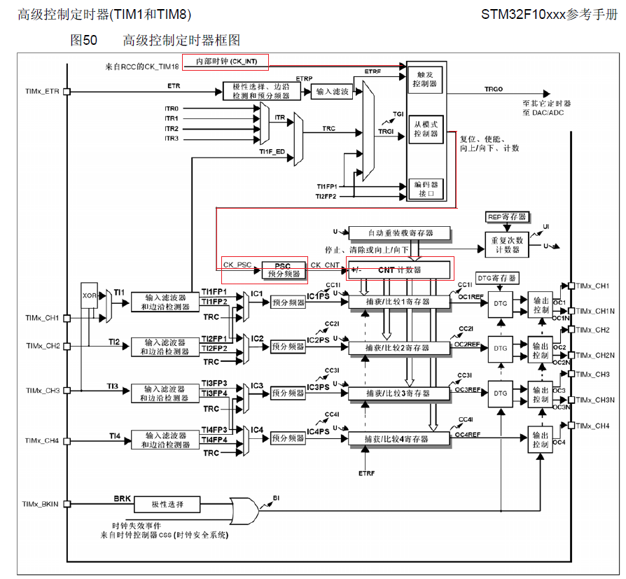
 1、选择定时器使用定时器首先要选择定时器,stm32f103zet6MCU芯片有8个定时器,其中TIM1和TIM8称为高级定时器,TIM2-TIM5称为通用定时器,TIM6和TIM7称为基本定时器,这里选择TIM1作为通用定时器功能使用。2、计算定时器配置参数在本程序中,想要通过TIM1进行1秒的定时,实现每秒钟产生一次定时计数溢出中断,然后在中断函数中调用数码管显示输出。由于系统初始化时钟(调用SystemInit函数)后APB2总线上的时钟为72MHz,本程序中TIM1的时钟选择为CK_INT,为72MHz,这个频率进过预分频和计数后得到1秒的定时,需要设置预分频系数与定时计数值之积为72M,这里设置预分频系数为7200,计数器计数值为10000。3、计数器配置编程① 使能TIM1时钟RCC_APB2PeriphClockCmd(RCC_APB2Periph_TIM1, ENABLE );② 配置TIM1参数typedef struct { uint16_t TIM_Prescaler; /*预分频系数. 取值0x0000-0xFFFF */ uint16_t TIM_CounterMode; /*计数模式*/ uint16_t TIM_Period; /*计数值 0x0000到 0xFFFF. */ uint16_t TIM_ClockDivision; /*!时钟分割,用于数字滤波器*/ uint8_t TIM_RepetitionCounter; /*重复次数,仅对TIM1和TIM8有意义. } TIM_TimeBaseInitTypeDef; 计数模式定义:#define TIM_CounterMode_Up ((uint16_t)0x0000) #define TIM_CounterMode_Down ((uint16_t)0x0010) #define TIM_CounterMode_CenterAligned1 ((uint16_t)0x0020) #define TIM_CounterMode_CenterAligned2 ((uint16_t)0x0040) #define TIM_CounterMode_CenterAligned3 ((uint16_t)0x0060) 时钟分割#define TIM_CKD_DIV1 ((uint16_t)0x0000) #define TIM_CKD_DIV2 ((uint16_t)0x0100) #define TIM_CKD_DIV4 ((uint16_t)0x0200) 程序如下:TIM_TimeBaseInitTypeDef TIM_TimeBaseStructure; //定义配置结构体变量TIM_TimeBaseStructure.TIM_Prescaler = (7200– 1);TIM_TimeBaseStructure.TIM_CounterMode =TIM_CounterMode_Up;TIM_TimeBaseStructure.TIM_Period = (10000 –1);TIM_TimeBaseStructure.TIM_ClockDivision =0;TIM_TimeBaseStructure.TIM_RepetitionCounter= 0;TIM_TimeBaseInit( TIM1,&TIM_TimeBaseStructure);③ 设置定时器中断类型,并使能。TIM_ITConfig(TIM1, TIM_IT_Update, ENABLE);④ 开启计数器,开始计数TIM_Cmd( TIM1, ENABLE);4、实现步骤① 在上述配置的项目中添加"tim.h"和"tim.c"文件,保存在"User/Tim"文件夹下,"tim.h"文件的内容为:#ifndef __TIM__H #define __TIM__H #include "system.h" #include "stm32f10x_rcc.h" #include "stm32f10x_tim.h" void Init_Tim(void); #endif "tim.c"文件内容为:#include "tim.h" void Tim_Init(void) { TIM_TimeBaseInitTypeDef TIM_TimeBaseStructure; //定义配置结构体变量 RCC_APB2PeriphClockCmd( RCC_APB2Periph_TIM1, ENABLE );//使能定时器TIM1时钟 TIM_TimeBaseStructure.TIM_Prescaler = (7200-1); TIM_TimeBaseStructure.TIM_CounterMode = TIM_CounterMode_Up; TIM_TimeBaseStructure.TIM_Period = (10000-1); TIM_TimeBaseStructure.TIM_ClockDivision = 0; TIM_TimeBaseStructure.TIM_RepetitionCounter = 0; TIM_TimeBaseInit( TIM1, &TIM_TimeBaseStructure); TIM_ClearITPendingBit(TIM1,TIM_IT_Update);//清除TIM1溢出中断标志 TIM_ITConfig(TIM1, TIM_IT_Update, ENABLE);//打开溢出中断 TIM_Cmd( TIM1, ENABLE); //启动定时器 } ② 将"tim.c"文件添加到项目的"User"组中;③ 将"./User/Tim"路径添加到项目文件包含的配置路径中(在"C/C++"选项卡中的"Include Paths"中)。 四、NVIC配置和中断函数1、配置中断分组(NVIC)NVIC_PriorityGroupConfig(NVIC_PriorityGroup_2);2、使能中断NVIC_InitTypeDef NVIC_InitStructure;NVIC_InitStructure.NVIC_IRQChannel =TIM1_UP_IRQn; //定时器1上溢中断NVIC_InitStructure.NVIC_IRQChannelPreemptionPriority= 0; //主优先级NVIC_InitStructure.NVIC_IRQChannelSubPriority=1;NVIC_InitStructure.NVIC_IRQChannelCmd =ENABLE;NVIC_Init( & NVIC_InitStructure);3、实现步骤① 在上述配置的项目中添加"nvic.h"和"nvic.c"文件,保存在"User/Nvic"文件夹下,"nvic.h"文件的内容为:#ifndef __NVIC__H #define __NVIC__H #include "stm32f10x.h" #include "misc.h" void My_NVIC_Init(void); #endif "nvic.c"文件内容为:#include "nvic.h" void My_NVIC_Init(void) { NVIC_InitTypeDef NVIC_InitStructure; NVIC_PriorityGroupConfig(NVIC_PriorityGroup_2 ); NVIC_InitStructure.NVIC_IRQChannel = TIM1_UP_IRQn; //定时器TIM1上溢中断 NVIC_InitStructure.NVIC_IRQChannelPreemptionPriority = 0; //主优先级 NVIC_InitStructure.NVIC_IRQChannelSubPriority=1; NVIC_InitStructure.NVIC_IRQChannelCmd = ENABLE; NVIC_Init( & NVIC_InitStructure); } ② 将"nvic.c"文件添加到项目的"User"组中;③ 将"./User/Nvic"路径添加到项目文件包含的配置路径中(在"C/C++"选项卡中的"Include Paths"中)。五、主函数和终端服务函数在main.c中添加中断服务函数TIM1_UP_IRQHandler,修改主函数,内容如下:#include "seg.h" #include "tim.h" #include "nvic.h" int main() { Seg_Init(); My_NVIC_Init(); Tim_Init(); Show(); while(1) { } } void TIM1_UP_IRQHandler(void) { Show(); TIM_ClearITPendingBit(TIM1, TIM_IT_Update); }

 要使得数码管正常显示需要进过以下步骤:1、使能GPIOC时钟2、配置GPIOC_0-GPIOC_7为推挽输出,50MHz速度3、通过库函数操作控制输出4、实现过程① 在上述配置的项目中添加"seg.h"和"seg.c"文件,保存在"User/Seg"文件夹下,"seg.h"文件的内容为:#ifndef __SEG__H #define __SEG__H #include "system.h" #include "stm32f10x_gpio.h" #define SEGPORT GPIOC #define SEG_RCCPORT RCC_APB2Periph_GPIOC #define SEGPIN (GPIO_Pin_0|GPIO_Pin_1|GPIO_Pin_2|GPIO_Pin_3|GPIO_Pin_4|GPIO_Pin_5|GPIO_Pin_6|GPIO_Pin_7) void Seg_Init(void); #endif "seg.c"文件的内容为:#include "seg.h" #include "stm32f10x_rcc.h" void Seg_Init() { GPIO_InitTypeDef GPIOC_mode; RCC_APB2PeriphClockCmd(SEG_RCCPORT, ENABLE); GPIOC_mode.GPIO_Pin = SEGPIN; GPIOC_mode.GPIO_Speed = GPIO_Speed_50MHz; GPIOC_mode.GPIO_Mode = GPIO_Mode_Out_PP; GPIO_Init(SEGPORT, &GPIOC_mode); } void Show() { static u8 n=0; u16 seg[10] = {0xc0,0xf9,0xa4,0xb0,0x99,0x92,0x82,0xf8,0x80,0x90}; GPIO_Write(SEGPORT, seg[n]); n++; n = n%10; } ② 将"seg.c"文件添加到项目的"User"组中;③ 将"./User/Seg"路径添加到项目文件包含的配置路径中(在"C/C++"选项卡中的"Include Paths"中)。三、定时器TIM1配置
 1、选择定时器使用定时器首先要选择定时器,stm32f103zet6MCU芯片有8个定时器,其中TIM1和TIM8称为高级定时器,TIM2-TIM5称为通用定时器,TIM6和TIM7称为基本定时器,这里选择TIM1作为通用定时器功能使用。2、计算定时器配置参数在本程序中,想要通过TIM1进行1秒的定时,实现每秒钟产生一次定时计数溢出中断,然后在中断函数中调用数码管显示输出。由于系统初始化时钟(调用SystemInit函数)后APB2总线上的时钟为72MHz,本程序中TIM1的时钟选择为CK_INT,为72MHz,这个频率进过预分频和计数后得到1秒的定时,需要设置预分频系数与定时计数值之积为72M,这里设置预分频系数为7200,计数器计数值为10000。3、计数器配置编程① 使能TIM1时钟RCC_APB2PeriphClockCmd(RCC_APB2Periph_TIM1, ENABLE );② 配置TIM1参数typedef struct { uint16_t TIM_Prescaler; /*预分频系数. 取值0x0000-0xFFFF */ uint16_t TIM_CounterMode; /*计数模式*/ uint16_t TIM_Period; /*计数值 0x0000到 0xFFFF. */ uint16_t TIM_ClockDivision; /*!时钟分割,用于数字滤波器*/ uint8_t TIM_RepetitionCounter; /*重复次数,仅对TIM1和TIM8有意义. } TIM_TimeBaseInitTypeDef; 计数模式定义:#define TIM_CounterMode_Up ((uint16_t)0x0000) #define TIM_CounterMode_Down ((uint16_t)0x0010) #define TIM_CounterMode_CenterAligned1 ((uint16_t)0x0020) #define TIM_CounterMode_CenterAligned2 ((uint16_t)0x0040) #define TIM_CounterMode_CenterAligned3 ((uint16_t)0x0060) 时钟分割#define TIM_CKD_DIV1 ((uint16_t)0x0000) #define TIM_CKD_DIV2 ((uint16_t)0x0100) #define TIM_CKD_DIV4 ((uint16_t)0x0200) 程序如下:TIM_TimeBaseInitTypeDef TIM_TimeBaseStructure; //定义配置结构体变量TIM_TimeBaseStructure.TIM_Prescaler = (7200– 1);TIM_TimeBaseStructure.TIM_CounterMode =TIM_CounterMode_Up;TIM_TimeBaseStructure.TIM_Period = (10000 –1);TIM_TimeBaseStructure.TIM_ClockDivision =0;TIM_TimeBaseStructure.TIM_RepetitionCounter= 0;TIM_TimeBaseInit( TIM1,&TIM_TimeBaseStructure);③ 设置定时器中断类型,并使能。TIM_ITConfig(TIM1, TIM_IT_Update, ENABLE);④ 开启计数器,开始计数TIM_Cmd( TIM1, ENABLE);4、实现步骤① 在上述配置的项目中添加"tim.h"和"tim.c"文件,保存在"User/Tim"文件夹下,"tim.h"文件的内容为:#ifndef __TIM__H #define __TIM__H #include "system.h" #include "stm32f10x_rcc.h" #include "stm32f10x_tim.h" void Init_Tim(void); #endif "tim.c"文件内容为:#include "tim.h" void Tim_Init(void) { TIM_TimeBaseInitTypeDef TIM_TimeBaseStructure; //定义配置结构体变量 RCC_APB2PeriphClockCmd( RCC_APB2Periph_TIM1, ENABLE );//使能定时器TIM1时钟 TIM_TimeBaseStructure.TIM_Prescaler = (7200-1); TIM_TimeBaseStructure.TIM_CounterMode = TIM_CounterMode_Up; TIM_TimeBaseStructure.TIM_Period = (10000-1); TIM_TimeBaseStructure.TIM_ClockDivision = 0; TIM_TimeBaseStructure.TIM_RepetitionCounter = 0; TIM_TimeBaseInit( TIM1, &TIM_TimeBaseStructure); TIM_ClearITPendingBit(TIM1,TIM_IT_Update);//清除TIM1溢出中断标志 TIM_ITConfig(TIM1, TIM_IT_Update, ENABLE);//打开溢出中断 TIM_Cmd( TIM1, ENABLE); //启动定时器 } ② 将"tim.c"文件添加到项目的"User"组中;③ 将"./User/Tim"路径添加到项目文件包含的配置路径中(在"C/C++"选项卡中的"Include Paths"中)。 四、NVIC配置和中断函数1、配置中断分组(NVIC)NVIC_PriorityGroupConfig(NVIC_PriorityGroup_2);2、使能中断NVIC_InitTypeDef NVIC_InitStructure;NVIC_InitStructure.NVIC_IRQChannel =TIM1_UP_IRQn; //定时器1上溢中断NVIC_InitStructure.NVIC_IRQChannelPreemptionPriority= 0; //主优先级NVIC_InitStructure.NVIC_IRQChannelSubPriority=1;NVIC_InitStructure.NVIC_IRQChannelCmd =ENABLE;NVIC_Init( & NVIC_InitStructure);3、实现步骤① 在上述配置的项目中添加"nvic.h"和"nvic.c"文件,保存在"User/Nvic"文件夹下,"nvic.h"文件的内容为:#ifndef __NVIC__H #define __NVIC__H #include "stm32f10x.h" #include "misc.h" void My_NVIC_Init(void); #endif "nvic.c"文件内容为:#include "nvic.h" void My_NVIC_Init(void) { NVIC_InitTypeDef NVIC_InitStructure; NVIC_PriorityGroupConfig(NVIC_PriorityGroup_2 ); NVIC_InitStructure.NVIC_IRQChannel = TIM1_UP_IRQn; //定时器TIM1上溢中断 NVIC_InitStructure.NVIC_IRQChannelPreemptionPriority = 0; //主优先级 NVIC_InitStructure.NVIC_IRQChannelSubPriority=1; NVIC_InitStructure.NVIC_IRQChannelCmd = ENABLE; NVIC_Init( & NVIC_InitStructure); } ② 将"nvic.c"文件添加到项目的"User"组中;③ 将"./User/Nvic"路径添加到项目文件包含的配置路径中(在"C/C++"选项卡中的"Include Paths"中)。五、主函数和终端服务函数在main.c中添加中断服务函数TIM1_UP_IRQHandler,修改主函数,内容如下:#include "seg.h" #include "tim.h" #include "nvic.h" int main() { Seg_Init(); My_NVIC_Init(); Tim_Init(); Show(); while(1) { } } void TIM1_UP_IRQHandler(void) { Show(); TIM_ClearITPendingBit(TIM1, TIM_IT_Update); }