{var%20f='http://v.t.sina.com.cn/share/share.php?appkey=1515056452',u=z||d.location,p=['&url=',e(u),'&title=',e(t||d.title),'&source=',e(r),'&sourceUrl=',e(l),'&content=',c||'gb2312','&pic=',e(p||'')].join('');function%20a(){if(!window.open([f,p].join(''),'mb',['toolbar=0,status=0,resizable=1,width=440,height=430,left=',(s.width-440)/2,',top=',(s.height-430)/2].join('')))u.href=[f,p].join('');};if(/Firefox/.test(navigator.userAgent))setTimeout(a,0);else%20a();})(screen,document,encodeURIComponent,'','','https://www.xiaopingtou.cn//data/attach/topic/topicKPo7gB.jpg', '推荐 寒剑孤影 的文章《CANoe9.0用CAPL控制数控电源》','https://www.xiaopingtou.net/article-85936.html','页面编码gb2312|utf-8默认gb2312'));)
1.前言
本文提供一种基于CAPL控制数控电源的方法,其实现原理是CAPL中调用RS232,发送SCPI指令与数控电源通信。
理论上,本文适用于串口通信的数控电源或其他串口设备。
2.开发环境
2.1硬件环境
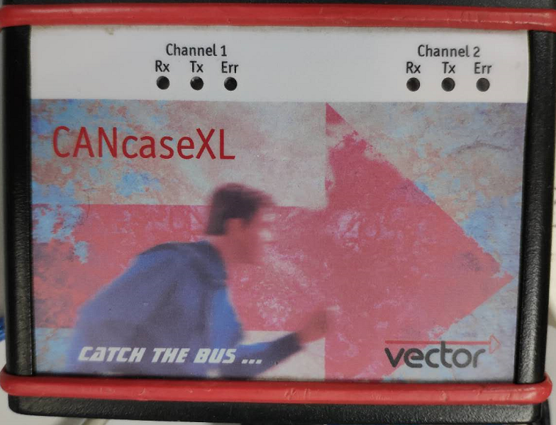
数控电源KORAD KA3005P,CANcaseXL

 2.2软件环境
CANoe 9.0,串口调试助手
3.参考资料
KA系列标准通信协议_百度文库 https://wenku.baidu.com/view/6adf09f1294ac850ad02de80d4d8d15abe230039.html
CANoe DEMO:File-Sample Configurations-IO HIL-RS232,这里是个使用RS232的DEMO
4.测试SCPI指令
将数控电源连上PC,注意,虽然是USB接口,但是数控电源内部虚拟了串口,可以在设备管理器中发现。
用串口助手打开电源的串口,设置波特率为9600(这里测试任何一个波特率都可以,不知为什么)。
然后以ASCII的方式发送指令。
这里测试的目的主要是为了验证通信。
具体的指令可以根据文档描述测试一下,这里就不细说了。
5.建立CANoe工程
创建个合适的工程,建立CAPL NODE,DBC,以及PANEL
2.2软件环境
CANoe 9.0,串口调试助手
3.参考资料
KA系列标准通信协议_百度文库 https://wenku.baidu.com/view/6adf09f1294ac850ad02de80d4d8d15abe230039.html
CANoe DEMO:File-Sample Configurations-IO HIL-RS232,这里是个使用RS232的DEMO
4.测试SCPI指令
将数控电源连上PC,注意,虽然是USB接口,但是数控电源内部虚拟了串口,可以在设备管理器中发现。
用串口助手打开电源的串口,设置波特率为9600(这里测试任何一个波特率都可以,不知为什么)。
然后以ASCII的方式发送指令。
这里测试的目的主要是为了验证通信。
具体的指令可以根据文档描述测试一下,这里就不细说了。
5.建立CANoe工程
创建个合适的工程,建立CAPL NODE,DBC,以及PANEL


 6.编辑CAPL代码
以下代码参考了Demo
6.编辑CAPL代码
以下代码参考了Demo
2.2软件环境
CANoe 9.0,串口调试助手
3.参考资料
KA系列标准通信协议_百度文库 https://wenku.baidu.com/view/6adf09f1294ac850ad02de80d4d8d15abe230039.html
CANoe DEMO:File-Sample Configurations-IO HIL-RS232,这里是个使用RS232的DEMO
4.测试SCPI指令
将数控电源连上PC,注意,虽然是USB接口,但是数控电源内部虚拟了串口,可以在设备管理器中发现。
用串口助手打开电源的串口,设置波特率为9600(这里测试任何一个波特率都可以,不知为什么)。
然后以ASCII的方式发送指令。
这里测试的目的主要是为了验证通信。
具体的指令可以根据文档描述测试一下,这里就不细说了。
5.建立CANoe工程
创建个合适的工程,建立CAPL NODE,DBC,以及PANEL
6.编辑CAPL代码
以下代码参考了Demo
/*@!Encoding:936*/
includes
{
}
variables
{
// GLOBAL
const int kBUFFER_SIZE = 1000;
const int kINFO = 1;
const int kWARN = 2;
const int kERROR = 3;
const int kHANDSHAKE_DISABLED = 0;
const int kHANDSHAKE_RTSCTS = 33;
// define for dp serial port com9
const dword port = 9;
const dword baudrate = 9600;
const dword dataBits = 8;
const dword stopBits = 1;
const dword parity = 0;//0:none 1:even 0:odd
// data is copied from callback buffer to gReceiverBuffer (collects data)
byte gReceiverCallbackBuffer[kBUFFER_SIZE];
byte gReceivedBuffer[kBUFFER_SIZE];
dword gReceivedIndex= 0;
// state variable
byte gSending = 0;
byte gGetValueSt = 0;
byte gSetValueSt = 0;
msTimer t100ms;
msTimer t20ms;
}
on preStart
{
InitSerialPort();
}
on start
{
setTimer(t100ms,100);
}
//RS232 Init
InitSerialPort()
{
// close serial port (port may have changed, former port shall not remain open)
if(Rs232Close(port)!=1)
writeLineEx(0,kERROR,"An error occurred during closing of the serial port %d.", port);
// set state (close aborts all open requests)
gSending = 0;
// open the serial port (comes up with Windows defaults)
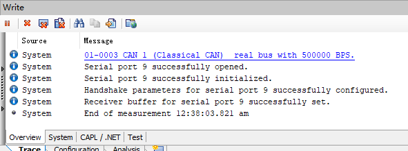
if(Rs232Open(port)==1)
writeLineEx(0,kINFO, "Serial port %d successfully opened.", port);
else
writeLineEx(0,kERROR,"An error occurred during opening of the serial port %d.", port);
// configure the serial port
// - just take the panel content
if(Rs232Configure(port,baudrate,dataBits,stopBits,parity)==1)
writeLineEx(0,kINFO, "Serial port %d successfully initialized.", port);
else
writeLineEx(0,kERROR,"An error occurred during initialization of the serial port %d.", port);
// port, handshake, xonLim, xoffLim, xonChar, xoffChar, writeTimeout
// without last timeout parameter: use default timeout
// for transmission of small amounts of data one may not need to use handshake !
// e.g. 33 for RTS/CTS as second parameter for large volumes of data, 0 for small volumes
if(Rs232SetHandshake(port, kHANDSHAKE_DISABLED, 0, 0, 0, 0))
writeLineEx(0,kINFO, "Handshake parameters for serial port %d successfully configured.", port);
else
writeLineEx(0,kERROR,"An error occurred during the serial port %d configuration of handshake parameters.", port);
// set buffer for reception (otherwise callback would not work)
if(Rs232Receive(port, gReceiverCallbackBuffer, kBUFFER_SIZE))
writeLineEx(0,kINFO, "Receiver buffer for serial port %d successfully set.", port);
else
writeLineEx(0,kERROR,"An error occurred during setting the receiver buffer for serial port %d.", port);
}
//RS232 Call back
RS232OnReceive( dword port, byte buffer[], dword number )
{
dword i;
for(i=0;i=5)
{
DP_DataRecevied(gReceivedBuffer,gReceivedIndex);
gReceivedIndex=0;
}
}
}
//RS232 Call back
RS232OnSend( dword port, byte buffer[], dword number )
{
// set state
gSending = 0;
//writeLineEx(0,kINFO,"Transmission of %d bytes from port %d completed !", number, port);
}
//RS232 Call back
RS232OnError( dword port, dword errorFlags )
{
// set state
gSending = 0;
writeLineEx(0,kERROR,"Error handler called with error code %d !", errorFlags);
if ( errorFlags & 1 )
writeLineEx(0,1,"%d informs of send error",errorFlags);
if ( errorFlags & 2 )
writeLineEx(0,1,"%d informs of receive error",errorFlags);
if ( errorFlags & 4 )
writeLineEx(0,1,"%d informs of frame error",errorFlags);
if ( errorFlags & 8 )
writeLineEx(0,1,"%d informs of parity error",errorFlags);
if ( errorFlags & 16 )
writeLineEx(0,1,"%d informs of overrun error",errorFlags);
if ( errorFlags & 32 )
writeLineEx(0,1,"%d informs of receiver overrun error",errorFlags);
if ( errorFlags & 64 )
writeLineEx(0,1,"%d informs of break state",errorFlags);
if ( errorFlags & 128 )
writeLineEx(0,1,"%d informs of send timeout error",errorFlags);
}
CopyBuffer( byte destBuffer[], dword destOffset, byte srcBuffer[], dword srcNumber )
{
dword i;
for (i=0; i3000)
writeLineEx(0,kERROR,"Voltage too high! ");
else
{
buf[i++]=(byte)(vol/1000)+0x30;
vol%=1000;
buf[i++]=(byte)(vol/100)+0x30;
vol%=100;
buf[i++]='.';
buf[i++]=(byte)(vol/10)+0x30;
buf[i++]=(byte)(vol%10)+0x30;
DP_Send(buf, i);
}
}
DP_SetCurrent(float data)
{
char str[7]="ISET1:";
char buf[100];
word vol=0;
byte i;
for(i=0; i<6; i++)
{
buf[i]=str[i];
}
vol = (word)(data*1000);
if(vol>5000)
writeLineEx(0,kERROR,"Current too high! ");
else
{
buf[i++]=(byte)(vol/1000)+0x30;
vol%=1000;
buf[i++]='.';
buf[i++]=(byte)(vol/100)+0x30;
vol%=100;
buf[i++]=(byte)(vol/10)+0x30;
buf[i++]=(byte)(vol%10)+0x30;
DP_Send(buf, i);
}
}
DP_DataRecevied(byte buffer[], dword len)
{
switch(gGetValueSt)
{
case 0:
putValue(Env_GetVoltage,AtoF(buffer,len));
gGetValueSt=1;
break;
case 1:
putValue(Env_GetCurrent,AtoF(buffer,len));
gGetValueSt=0;
break;
default:
break;
}
}
float AtoF(byte buffer[], dword len)
{
double getData;
dword i;
byte flag;
dword per;
getData = 0;//static
per=1;//static
flag=0;//static
for(i=0; i
7.测试


 8.总结
(1)CANoe十分强大,可以干很多事情,本文中的方法也只是众多控制数控电源方式中的一种,本人未开发过基于CANoe的自动化测试设备,也并不清楚并不清楚商业上是如何实现的。
(2)DEMO很有参考价值,不会的可以找DEMO参考
(3)他节点可以通过调用dbc中定义的环境变量,来获取或者设置电源的电压电流
(4)win10微软拼音在360浏览器编辑此贴,打字会抽风
8.总结
(1)CANoe十分强大,可以干很多事情,本文中的方法也只是众多控制数控电源方式中的一种,本人未开发过基于CANoe的自动化测试设备,也并不清楚并不清楚商业上是如何实现的。
(2)DEMO很有参考价值,不会的可以找DEMO参考
(3)他节点可以通过调用dbc中定义的环境变量,来获取或者设置电源的电压电流
(4)win10微软拼音在360浏览器编辑此贴,打字会抽风