{var%20f='http://v.t.sina.com.cn/share/share.php?appkey=1515056452',u=z||d.location,p=['&url=',e(u),'&title=',e(t||d.title),'&source=',e(r),'&sourceUrl=',e(l),'&content=',c||'gb2312','&pic=',e(p||'')].join('');function%20a(){if(!window.open([f,p].join(''),'mb',['toolbar=0,status=0,resizable=1,width=440,height=430,left=',(s.width-440)/2,',top=',(s.height-430)/2].join('')))u.href=[f,p].join('');};if(/Firefox/.test(navigator.userAgent))setTimeout(a,0);else%20a();})(screen,document,encodeURIComponent,'','','https://www.xiaopingtou.cn//data/attach/topic/topicKPo7gB.jpg', '推荐 风的海洋 的文章《OpenCV根据矩形轮廓进行倾斜校正》','https://www.xiaopingtou.net/article-93051.html','页面编码gb2312|utf-8默认gb2312'));)
本文将介绍如何利用OpenCV,提取图片中的矩形轮廓特征并进行图片的倾斜校正。完成demo程序可以至:OpenCV根据矩形轮廓进行倾斜校正下载。
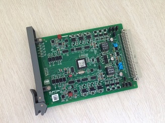
本demo所处理的图片是一张PCB电路板(如下图),欲实现的功能是将图片中倾斜的PCB校正为水平。基本的思路是检测PCB的边缘直线,而后根据边缘直线的斜率旋转图片。但是由于PCB上布满了各种原件,所以图片在经过轮廓提取直线检测后,会误检出很多条直线。demo程序中主要的算法就是从含有噪声的直线簇中提取出直线中相互垂直的直线。
 Step1: 直线检测。OpenCV提供了一个检测直线的函数HoughLinesP(),关于此函数的API介绍,可以参考HoughLinesP。此步骤主要程序如下:

上图为使用Canny算子检测出的边缘。PCB板上驳杂分布的原件使得算法检测出了丰富的轮廓信息。对此轮廓图进行直线检测,结果如下图所示,除了PCB的边缘直线被检测出来, 算法还误检出了很多的直线。因此,下一步算法的目的就是提取边缘直线,滤出PCB板内的误检直线。
 Step2:直线滤波。PCB边缘直线与误检直线所具有的一个不同特征是边缘直线相互垂直,误检直线不一定能找到与其相垂直的直线。算法利用此特征对所有检测出的直线进行滤波。
垂直条件的直线
 Step3:倾角计算。
滤波后的直线簇中可能会存在与边缘直线相平行的直线,因此通过对std::vector lineFiltered进行四次排序,提取出最靠图像边界的直线。排序规则即为分别对线段中点坐标x,y的值升序降序排列。注意,在图像坐标系中,原点是图像的最左上角。
计算边缘直线的斜率。下面的程序中angleForCorrect()函数返回的是图像最终需要旋转的角度。
上图中,检测到的PCB最下方的直线虽然不是真正PCB的边缘直线,但也是与之平行的直线。因此对于计算倾斜角度来说,这个误差在可接受范围内。 Step4:图像旋转。
根据上一步得到的倾斜角度,用以下函数旋转图片,校正倾斜。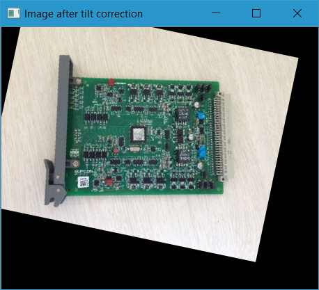
Step1: 直线检测。OpenCV提供了一个检测直线的函数HoughLinesP(),关于此函数的API介绍,可以参考HoughLinesP。此步骤主要程序如下:
Mat imgOrigion = imread(IMAGE_PATH);
Mat imgScale;
float scaleFactor = COLSLIMIT / imgOrigion.cols;
resize(imgOrigion, imgScale, Size(imgOrigion.cols * scaleFactor, imgOrigion.rows * scaleFactor)); // reduce image size to speed up calculation
Mat imgGray;
cvtColor(imgScale, imgGray, COLOR_BGR2GRAY); // gray scale
Mat imgCanny;
Canny(imgGray, imgCanny, 100, 200); // use canny operator to detect contour
imshow("Contour detection", imgCanny);
std::vector
上图为使用Canny算子检测出的边缘。PCB板上驳杂分布的原件使得算法检测出了丰富的轮廓信息。对此轮廓图进行直线检测,结果如下图所示,除了PCB的边缘直线被检测出来, 算法还误检出了很多的直线。因此,下一步算法的目的就是提取边缘直线,滤出PCB板内的误检直线。
Step2:直线滤波。PCB边缘直线与误检直线所具有的一个不同特征是边缘直线相互垂直,误检直线不一定能找到与其相垂直的直线。算法利用此特征对所有检测出的直线进行滤波。
std::list
下图即为所有符合 垂直条件的直线
Step3:倾角计算。 滤波后的直线簇中可能会存在与边缘直线相平行的直线,因此通过对std::vector lineFiltered进行四次排序,提取出最靠图像边界的直线。排序规则即为分别对线段中点坐标x,y的值升序降序排列。注意,在图像坐标系中,原点是图像的最左上角。
计算边缘直线的斜率。下面的程序中angleForCorrect()函数返回的是图像最终需要旋转的角度。
double correctAngle = 0.0;  // average tilt angle of PCB
if (lineFiltered.size() > 0)
{
    // find edge lines of PCB
    std::vector lineEdge;
    sort(lineFiltered.begin(), lineFiltered.end(), getMinMidX);  // get the line at the far left of the image
    lineEdge.push_back(lineFiltered[0]);
    sort(lineFiltered.begin(), lineFiltered.end(), getMaxMidX);  // get the line at the far right of the image
    lineEdge.push_back(lineFiltered[0]);
    sort(lineFiltered.begin(), lineFiltered.end(), getMinMidY);  // get the line at the top of the image
    lineEdge.push_back(lineFiltered[0]);
    sort(lineFiltered.begin(), lineFiltered.end(), getMaxMidY);  // get the line at the buttom of the image
    lineEdge.push_back(lineFiltered[0]);

    Mat imgLinesEdge;
    imgScale.copyTo(imgLinesEdge);
    // draw lines after filtering
    for (int i = 0, steps = lineEdge.size(); i < steps; i++)
    {
        line(imgLinesEdge, Point(lineEdge[i][0], lineEdge[i][1]), Point(lineEdge[i][2], lineEdge[i][3]), Scalar(0, 0, 255), 3, 8);
    }
    imshow("PCB edge lines", imgLinesEdge);

    for (int i = 0, step = lineEdge.size(); i < step; i++)   // calcualte averge tilt angle of PCB edge lines
    {
        correctAngle += angleForCorrect(lineEdge[i]);
    }
    correctAngle /= lineEdge.size();
}

/**
* @brief comparison function for sort, sort vector from small to large accodoring to x of the midpoint of each element
* @param line1
* @param line2
* @return
*/
bool getMinMidX(const cv::Vec4i& line1, const cv::Vec4i& line2)
{
    return (line1[0] + line1[2]) < (line2[0] + line2[2]); // Although middle point compared, there is no need to divide 2
}

/**
* @brief comparison function for sort, sort vector from large to small accodoring to x of the midpoint of each element
* @param line1
* @param line2
* @return
*/
bool getMaxMidX(const cv::Vec4i& line1, const cv::Vec4i& line2)
{
    return (line1[0] + line1[2]) > (line2[0] + line2[2]);
}

/**
* @brief comparison function for sort, sort vector from small to large accodoring to y of the midpoint of each element
* @param line1
* @param line2
* @return
*/
bool getMinMidY(const cv::Vec4i& line1, const cv::Vec4i& line2)
{
    return (line1[1] + line1[3]) < (line2[1] + line2[3]);
}

/**
* @brief comparison function for sort, sort vector from large to small accodoring to y of the midpoint of each element
* @param line1
* @param line2
* @return
*/
bool getMaxMidY(const cv::Vec4i& line1, const cv::Vec4i& line2)
{
    return (line1[1] + line1[3]) > (line2[1] + line2[3]);
}

/**
* @brief rotation angle in degrees for correcting tilt
* @param line: for cv::Vec4i& line, [0] is always smaller than [2]
* @return The symbol of the result represnts the direction of rotation to correct tilt.
*         Positive values mean counter-clockwise rotation (the coordinate origin is assumed to be the top-left corner).
*/
double angleForCorrect(const cv::Vec4i& line)
{
    Vec4i unitXVector(0, 0, 1, 0);
    double angle = angleOfLines(unitXVector, line);  // here angle belongs to [0, pi/2]
    // @attention: the increment direction of X and Y axis of OpenCV is different from usual rectangular coordinate system. The origin point is in the upper left corner of the image
    if (angle < 45)
    {
        // consider in the horizontal direction
        if (line[1] > line[3])
        {
            angle = -angle;
        }
    }
    else
    {
        // consider in the vertical direction
        if (line[1] > line[3])
        {
            angle = 90 - angle;
        }
        else
        {
            angle = angle - 90;
        }
    }

    return angle;
}
上图中,检测到的PCB最下方的直线虽然不是真正PCB的边缘直线,但也是与之平行的直线。因此对于计算倾斜角度来说,这个误差在可接受范围内。 Step4:图像旋转。
根据上一步得到的倾斜角度,用以下函数旋转图片,校正倾斜。
/**
* @brief rotate iamge according to angle
* @param src
* @param dst
* @param angle: rotation angle in degrees. Positive values mean counter-clockwise rotation (the
coordinate origin is assumed to be the top-left corner).
*/
void rotateIamge(cv::Mat& src, cv::Mat& dst, double angle)
{
    cv::Point2f center(src.cols / 2, src.rows / 2);
    cv::Mat rot = getRotationMatrix2D(center, angle, 1);
    cv::Rect box = RotatedRect(center, src.size(), angle).boundingRect(); // get circumscribed rectangle
    cv::warpAffine(src, dst, rot, box.size());
}