{var%20f='http://v.t.sina.com.cn/share/share.php?appkey=1515056452',u=z||d.location,p=['&url=',e(u),'&title=',e(t||d.title),'&source=',e(r),'&sourceUrl=',e(l),'&content=',c||'gb2312','&pic=',e(p||'')].join('');function%20a(){if(!window.open([f,p].join(''),'mb',['toolbar=0,status=0,resizable=1,width=440,height=430,left=',(s.width-440)/2,',top=',(s.height-430)/2].join('')))u.href=[f,p].join('');};if(/Firefox/.test(navigator.userAgent))setTimeout(a,0);else%20a();})(screen,document,encodeURIComponent,'','','https://www.xiaopingtou.cn//data/attach/topic/topicKPo7gB.jpg', '推荐 wangyalong_ 的文章《基于OpenCV的PCB缺损判断研究》','https://www.xiaopingtou.net/article-93939.html','页面编码gb2312|utf-8默认gb2312'));)
本人模式识别小硕一枚,目前帝都某校研一在读。寒假自己用opencv做了一个对PCB板的好坏的检测,拿出来和大家一起学习讨论,这篇博文也是我在CSDN上发表的第一篇文章,欢迎各路大神指导。
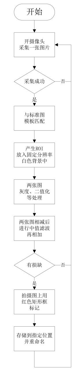 基本思想是通过定焦的工业摄像头,对放置于卡槽中的PCB进行拍摄并取ROI,与标准的PCB图片进行模板匹配,两者二值化后相减并中值滤波,在缺损处用红 {MOD}矩形标出,最后只命名输出缺损PCB图片。
为了给大家更好的演示,我将程序改为直接读取图片。
程序如下:
基本思想是通过定焦的工业摄像头,对放置于卡槽中的PCB进行拍摄并取ROI,与标准的PCB图片进行模板匹配,两者二值化后相减并中值滤波,在缺损处用红 {MOD}矩形标出,最后只命名输出缺损PCB图片。
为了给大家更好的演示,我将程序改为直接读取图片。
程序如下:
(可能有些杂乱,本人水平还需提高)
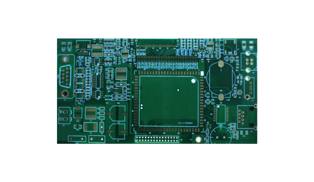
【完好无损的PCB】
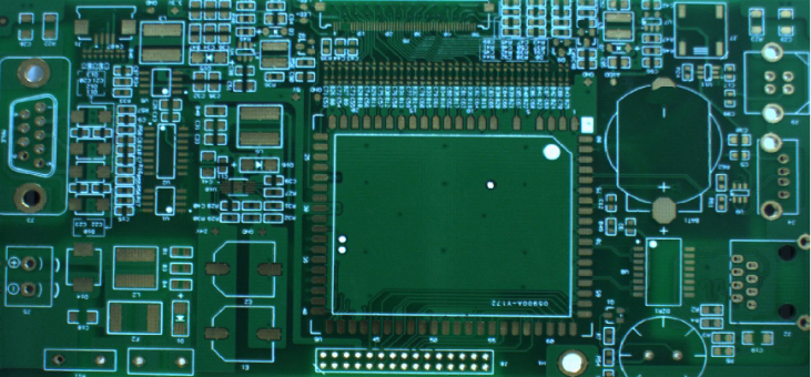
【有缺损的PCB】(焊盘缺失或缺损)
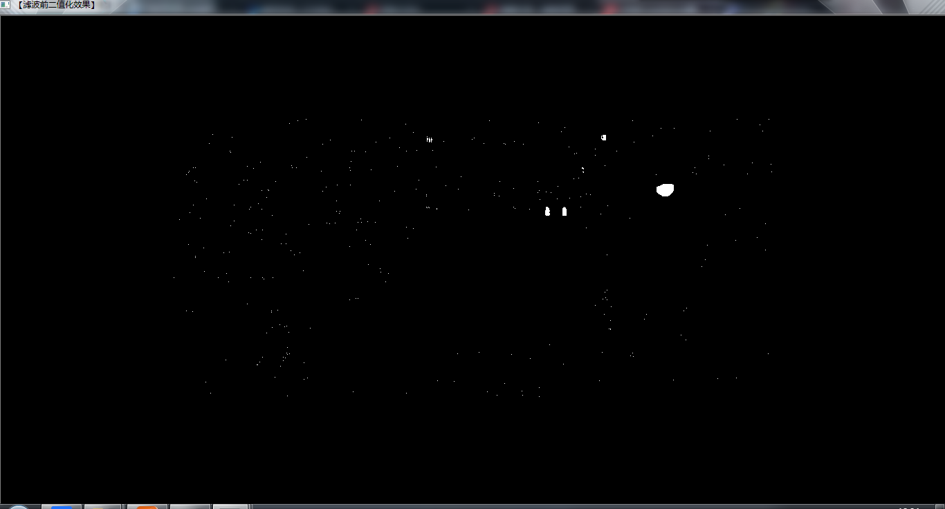
【处理后未滤波的图片】

【滤波后图像】
【缺损判断标记】(图上红 {MOD}矩形框) 程序中Wback是读入的一张纯白 {MOD}底板图片,这个底板分辨率和标准模板图片一致,为了在模板匹配后相减时防止检测图片因拍摄或放PCB板入卡槽时,位置的改变而处理的。 还有太多的东西需要学习,欢迎大神前辈们指教。
基本思想是通过定焦的工业摄像头,对放置于卡槽中的PCB进行拍摄并取ROI,与标准的PCB图片进行模板匹配,两者二值化后相减并中值滤波,在缺损处用红 {MOD}矩形标出,最后只命名输出缺损PCB图片。
为了给大家更好的演示,我将程序改为直接读取图片。
程序如下: (可能有些杂乱,本人水平还需提高)
/********************************************************************************/
/*
* Copyright(c)2016
* ALL rights reserved.
*
* file name: Lab_Identification_Program.cpp
* file description:
*
* Abstract:
* current version:2.0
* author: L T
* date: 2016.2.3
*
* replacement version:
* original author:
* date:
*/
/********************************************************************************/
#include(i); //获取第i行的首地址
for(int j = 0;j < colNumber;j++) //列循环
{
// ---------【开始处理每个像素】-------------
//data[j] = data[j]/div*div + div/2;
if(data[j]==255)//如果白 {MOD}
{
//imshow("【效果图】Canny边缘检测", grayImage);
imwrite("有问题的PCB.jpg",WbackClone1);
ConditionJudgment=0;
break;
}
// ----------【处理结束】---------------------
} //行处理结束
}
}
//------------------------------------------------------
// 主程序
//------------------------------------------------------
int main()
{
//CallCamera();//调用摄像头
namedWindow("【滤波前二值化效果】", 2);
namedWindow("【滤波后缺损二值化显示】", 2);
namedWindow("【对拍摄图缺损位置进行标注】", 2);
namedWindow("【彩 {MOD}ROI位置待判断图】", 2);
ReadPic();//读入图片
Binarization();//二值化
TempMatch();//模板匹配
subtract(srcImage,WbackClone,img_result1);//相减
subtract(WbackClone,srcImage,img_result2);
medianBlur(img_result1,img_result,3);//小噪点使用中值滤波 或 erode + dilate方案 3
medianBlur(img_result2,img_result2,3);
//GaussianBlur(img_result1,img_result,Size(3,3),0,0);//高斯滤波
//adaptiveThreshold(img, dst, 255, ADAPTIVE_THRESH_MEAN_C, THRESH_BINARY,3,5);
add(img_result,img_result2,img_result);//两幅互减图叠加
Mat ele = getStructuringElement(MORPH_RECT, Size(5,5));
dilate(img_result,img_result,ele);
Mat threshold_output;
vector<vector0, 0, 255 );
//rectangle( drawing, boundRect[i].tl(), boundRect[i].br(), color, 2, 8, 0 );//效果图上绘制矩形
rectangle( WbackClone1, boundRect[i].tl(), boundRect[i].br(), color, 2, 8, 0 );//原图上绘制矩形
}
DefectJudgment();//缺损判断
imshow( "【滤波前二值化效果】", img_result1 );
imshow( "【滤波后缺损二值化显示】", img_result );
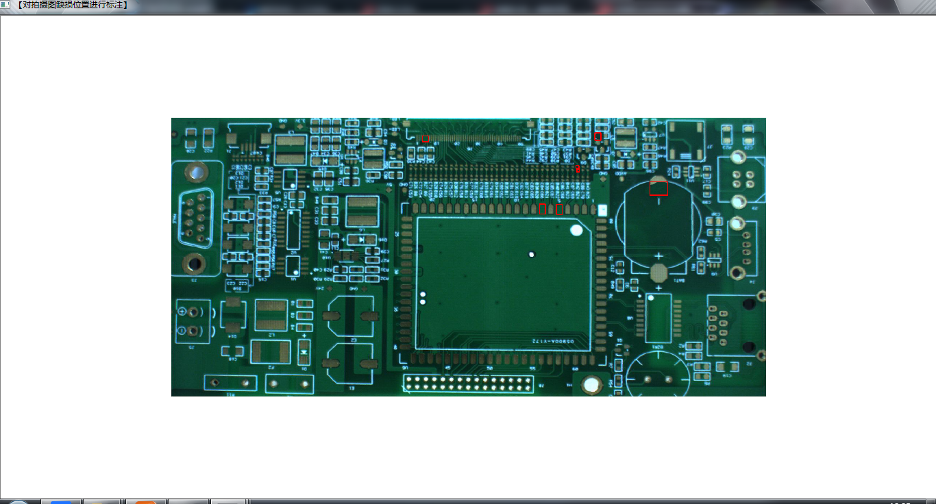
imshow( "【对拍摄图缺损位置进行标注】", WbackClone1 );
waitKey(0);
}
效果如下图所示: 【完好无损的PCB】
【有缺损的PCB】(焊盘缺失或缺损)
【处理后未滤波的图片】
【滤波后图像】
【缺损判断标记】(图上红 {MOD}矩形框) 程序中Wback是读入的一张纯白 {MOD}底板图片,这个底板分辨率和标准模板图片一致,为了在模板匹配后相减时防止检测图片因拍摄或放PCB板入卡槽时,位置的改变而处理的。 还有太多的东西需要学习,欢迎大神前辈们指教。