STM32F103RBT6驱动UC1698控制芯片的160*160黑白点阵液晶的程序,在上面移植了ZLG_GUI
2019-12-12 18:20发布
{var%20f='http://v.t.sina.com.cn/share/share.php?appkey=1515056452',u=z||d.location,p=['&url=',e(u),'&title=',e(t||d.title),'&source=',e(r),'&sourceUrl=',e(l),'&content=',c||'gb2312','&pic=',e(p||'')].join('');function%20a(){if(!window.open([f,p].join(''),'mb',['toolbar=0,status=0,resizable=1,width=440,height=430,left=',(s.width-440)/2,',top=',(s.height-430)/2].join('')))u.href=[f,p].join('');};if(/Firefox/.test(navigator.userAgent))setTimeout(a,0);else%20a();})(screen,document,encodeURIComponent,'','','https://www.xiaopingtou.cn/data/attach/logo/logo.png', '推荐 soulcoffee 的问题《STM32F103RBT6驱动UC1698控制芯片的160*160黑白点阵液晶的程序,在上面移植了ZLG_GUI》','https://www.xiaopingtou.net/q-157255.html','页面编码gb2312|utf-8默认gb2312'));)
STM32F103RBT6驱动UC1698控制芯片的160*160黑白点阵液晶的程序,在上面移植了ZLG_GUI.
由于本人刚接触STM32,本想移植UCGUI,发现UCGUI比较复杂,一时半会搞不明白,黑白液晶的也发挥不了UCGUI的特长,
先移植了ZLG的,这款160*160的液晶在电力行业用的比较多。
请轻些拍砖。
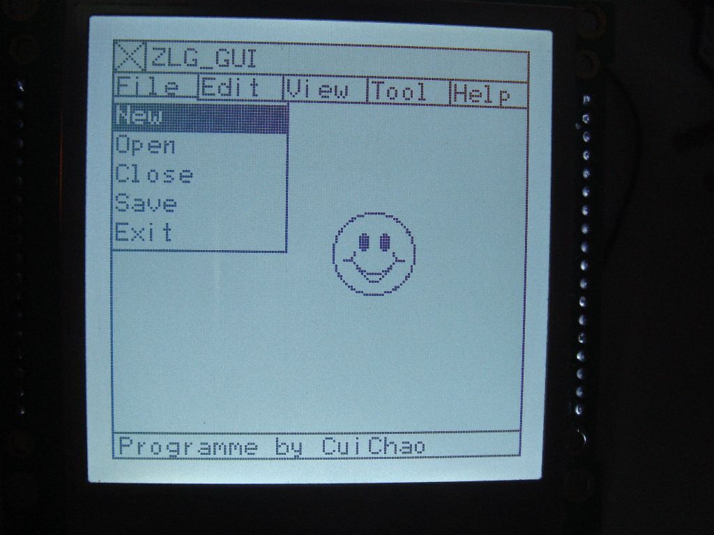
(原文件名:DSC00086.JPG)
点击此处下载 ourdev_523183.rar(文件大小:222K) (原文件名:KEIL_STM32.rar)
由于本人刚接触STM32,本想移植UCGUI,发现UCGUI比较复杂,一时半会搞不明白,黑白液晶的也发挥不了UCGUI的特长,
先移植了ZLG的,这款160*160的液晶在电力行业用的比较多。
请轻些拍砖。
(原文件名:DSC00086.JPG)
点击此处下载 ourdev_523183.rar(文件大小:222K) (原文件名:KEIL_STM32.rar)
友情提示: 此问题已得到解决,问题已经关闭,关闭后问题禁止继续编辑,回答。
void LCD_Pins_Config(void)
{
GPIO_InitTypeDef GPIO_InitStructure;
RCC_APB2PeriphClockCmd(RCC_APB2Periph_GPIOC | RCC_APB2Periph_GPIOE , ENABLE);
/*配置160*160数据端口*/
GPIO_InitStructure.GPIO_Pin = GPIO_Pin_8 | GPIO_Pin_9 | GPIO_Pin_10 |
GPIO_Pin_11 | GPIO_Pin_12 | GPIO_Pin_13 |
GPIO_Pin_14 | GPIO_Pin_15;
GPIO_InitStructure.GPIO_Speed = GPIO_Speed_50MHz;
GPIO_InitStructure.GPIO_Mode = GPIO_Mode_Out_PP;
GPIO_Init(GPIOE, &GPIO_InitStructure);
/*配置160*160控制端口*/
//LCD_Pin_WR
GPIO_InitStructure.GPIO_Pin = GPIO_Pin_6;
GPIO_InitStructure.GPIO_Speed = GPIO_Speed_50MHz;
GPIO_InitStructure.GPIO_Mode = GPIO_Mode_Out_PP;
GPIO_Init(GPIOE, &GPIO_InitStructure);
//LCD_Pin_RS
GPIO_InitStructure.GPIO_Pin = GPIO_Pin_5;
GPIO_InitStructure.GPIO_Speed = GPIO_Speed_50MHz;
GPIO_InitStructure.GPIO_Mode = GPIO_Mode_Out_PP;
GPIO_Init(GPIOE, &GPIO_InitStructure);
//LCD_Pin_RD
GPIO_InitStructure.GPIO_Pin = GPIO_Pin_7;
GPIO_InitStructure.GPIO_Speed = GPIO_Speed_50MHz;
GPIO_InitStructure.GPIO_Mode = GPIO_Mode_IPD;
GPIO_Init(GPIOE, &GPIO_InitStructure);
//LCD_Pin_BLK
GPIO_InitStructure.GPIO_Pin = GPIO_Pin_0;
GPIO_InitStructure.GPIO_Speed = GPIO_Speed_50MHz;
GPIO_InitStructure.GPIO_Mode = GPIO_Mode_Out_PP;
GPIO_Init(GPIOC, &GPIO_InitStructure);
//LCD_Pin_CS
GPIO_InitStructure.GPIO_Pin = GPIO_Pin_6;
GPIO_InitStructure.GPIO_Speed = GPIO_Speed_50MHz;
GPIO_InitStructure.GPIO_Mode = GPIO_Mode_Out_PP;
GPIO_Init(GPIOC, &GPIO_InitStructure);
//LCD_Pin_RES
GPIO_InitStructure.GPIO_Pin = GPIO_Pin_7;
GPIO_InitStructure.GPIO_Speed = GPIO_Speed_50MHz;
GPIO_InitStructure.GPIO_Mode = GPIO_Mode_Out_PP;
GPIO_Init(GPIOC, &GPIO_InitStructure);
}
void SdCmd(u8 Command)
{
ClrRs(); //选择指令通道
SetRd();
ClrCs(); // 选择模块
LCD_Write(Command << 8); // 将指令送至数据接口
ClrWr(); // 写信号为低电平
// Delay(1000);
SetWr(); // 写信号为高电平
SetCs(); // 封锁模块
}
void SdData(u8 Ddata)
{
SetRs(); // 选择数据通道
SetRd();
ClrCs();
LCD_Write(Ddata << 8); // 将指令送至数据接口
ClrWr(); // 写信号为低电平
// Delay(1000);
SetWr(); // 写信号为高电平
SetCs(); // 封锁模块
}
void initLCDM(void)
{
ClrRES(); Delay(1000); //硬件复位
SetRES(); Delay(80000); //复位后延迟800ms以上时间
SetBlk();
ContrastLevel=0xbf;
SdCmd(0x25); // 设置温度补偿系数-0.05%/C
SdCmd(0x2b); // 内部DC-DC
SdCmd(0xc4); // LCD映像MY=1,MX=0,LC0=0
SdCmd(0xa3); // 设置行扫描频率
SdCmd(0xd1); // 彩 {MOD}数据格式R-G-B
SdCmd(0xd5); // 设置数据位为12位RRRR-GGGG-BBBB
SdCmd(0xc8); SdCmd(0x00); // 设置M信号为0行翻砖
SdCmd(0xe9); // 设置偏压比1/10
SdCmd(0xa6); // 正性显示
SdCmd(0xa4); // 正常显示
SdCmd(0x81); SdCmd(ContrastLevel); //设置对比度bf
SdCmd(0xd8); // 设置扫描模式
SdCmd(0xad); // 开显示
}
int main(void)
{
SystemInit(); //系统初始化
LCD_Pins_Config();
SetRES();
SetCs();
Set_DB();
SetWr();
SetRd();
initLCDM();
ShowBMP(0,0,160,160,DISPLOGO);
}
拜谢
一周热门 更多>