本帖最后由 littleshrimp 于 2017-10-24 17:19 编辑
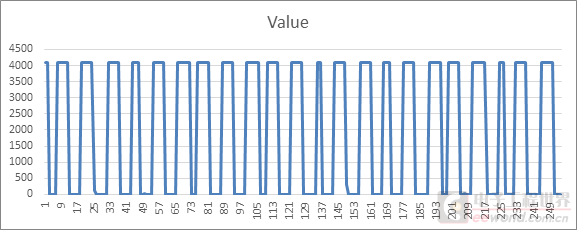
数据手册上说STM32L452的ADC最大支持5.33MSPS为了验证ADC的采样率使用一个单片机产生10KHz的方波,50%占空比将输出连接到STM32L542的ADC输入引脚 STM32L542的ADC使用系统时钟不分频,系统时钟为80MHz使用12位分辨率,开始的时候使用DMA方式,数据长度为4096使用STM32Cube_FW_L4_V1.9.0中的ADC_DMA_Transfer例程Sampling time设置为640.5cycles时采样到的波形如下
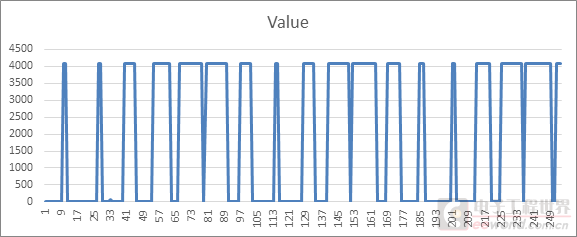
Sampling time设置为247.5 cycles时采样到的波形如下可以看到,使用DMA时采到的数据一点规律没有
DMA测试代码
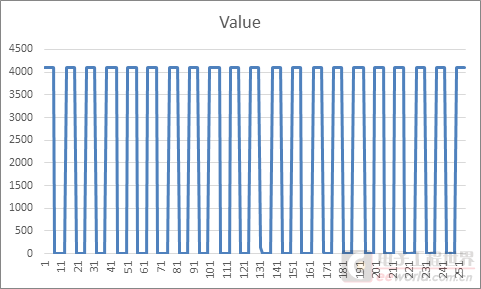
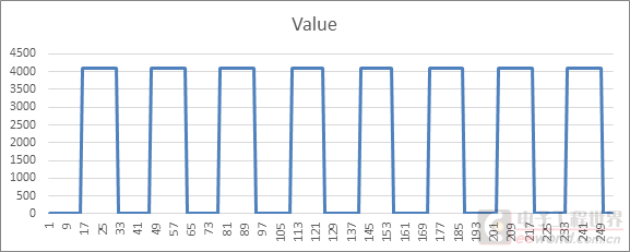
实际采样率为10KHz*12 = 120KSPS理论采样率为80MHz/(640.9+12.5) = 122.5KSPS理论和实际基本一致 采样时间设置为247.5时采集到的数据,高电平15个样本低电平15个样本,一个周期共采集30个样本
实际采样率为10KHz*30=300KSPS理论采样率为80MHz/(247.5+12.5) = 307.6KSPS理论和实际基本一致 将SamplingTime改为92.5时高低电平各26个,一个周期为52个样本
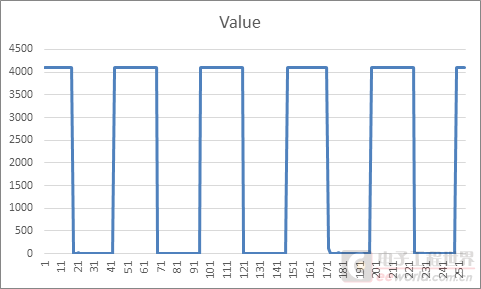
实际采样率为10KHz * 52 = 520KSPS 理论采样率为80MHz / (92.5+12.5) = 761.9KSPS 实际采样率比理论低很多,是理论采样率的68.2% 将SamplingTime改为47.5时高低电平各31个,一个周期为62个样本
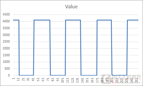
实际采样率为10KHz * 62= 620KSPS 理论采样率为80MHz / (47.5+12.5) = 1333.3KSPS 实际采样率比理论低很多,是理论采样率的46.5% ADC_RegularConversion_Interrupt测试代码
此帖出自小平头技术问答
数据手册上说STM32L452的ADC最大支持5.33MSPS为了验证ADC的采样率使用一个单片机产生10KHz的方波,50%占空比将输出连接到STM32L542的ADC输入引脚 STM32L542的ADC使用系统时钟不分频,系统时钟为80MHz使用12位分辨率,开始的时候使用DMA方式,数据长度为4096使用STM32Cube_FW_L4_V1.9.0中的ADC_DMA_Transfer例程Sampling time设置为640.5cycles时采样到的波形如下


- /**
- ******************************************************************************
- * @file ADC/ADC_DMA_Transfer/Src/main.c
- * @author MCD Application Team
- * [url=home.php?mod=space&uid=159083]@brief[/url] This example describes how to use the DMA to convert continuously data.
- ******************************************************************************
- * @attention
- *
- * <h2><center>© COPYRIGHT(c) 2017 STMicroelectronics</center></h2>
- *
- * Redistribution and use in source and binary forms, with or without modification,
- * are permitted provided that the following conditions are met:
- * 1. Redistributions of source code must retain the above copyright notice,
- * this list of conditions and the following disclaimer.
- * 2. Redistributions in binary form must reproduce the above copyright notice,
- * this list of conditions and the following disclaimer in the documentation
- * and/or other materials provided with the distribution.
- * 3. Neither the name of STMicroelectronics nor the names of its contributors
- * may be used to endorse or promote products derived from this software
- * without specific prior written permission.
- *
- * THIS SOFTWARE IS PROVIDED BY THE COPYRIGHT HOLDERS AND CONTRIBUTORS "AS IS"
- * AND ANY EXPRESS OR IMPLIED WARRANTIES, INCLUDING, BUT NOT LIMITED TO, THE
- * IMPLIED WARRANTIES OF MERCHANTABILITY AND FITNESS FOR A PARTICULAR PURPOSE ARE
- * DISCLAIMED. IN NO EVENT SHALL THE COPYRIGHT HOLDER OR CONTRIBUTORS BE LIABLE
- * FOR ANY DIRECT, INDIRECT, INCIDENTAL, SPECIAL, EXEMPLARY, OR CONSEQUENTIAL
- * DAMAGES (INCLUDING, BUT NOT LIMITED TO, PROCUREMENT OF SUBSTITUTE GOODS OR
- * SERVICES; LOSS OF USE, DATA, OR PROFITS; OR BUSINESS INTERRUPTION) HOWEVER
- * CAUSED AND ON ANY THEORY OF LIABILITY, WHETHER IN CONTRACT, STRICT LIABILITY,
- * OR TORT (INCLUDING NEGLIGENCE OR OTHERWISE) ARISING IN ANY WAY OUT OF THE USE
- * OF THIS SOFTWARE, EVEN IF ADVISED OF THE POSSIBILITY OF SUCH DAMAGE.
- *
- ******************************************************************************
- */
- /* Includes ------------------------------------------------------------------*/
- #include "main.h"
- /** @addtogroup STM32L4xx_HAL_Examples
- * @{
- */
- /** @addtogroup ADC_DMA_Transfer
- * @{
- */
- /* Private typedef -----------------------------------------------------------*/
- /* Private define ------------------------------------------------------------*/
- /* Definitions of data related to this example */
- /* Definition of ADCx conversions data table size */
- #define ADC_CONVERTED_DATA_BUFFER_SIZE ((uint32_t) 4096) /* Size of array aADCxConvertedData[] */
- /* Private macro -------------------------------------------------------------*/
- /* Private variables ---------------------------------------------------------*/
- /* ADC handle declaration */
- ADC_HandleTypeDef AdcHandle;
- /* ADC channel configuration structure declaration */
- ADC_ChannelConfTypeDef sConfig;
- /* Variable containing ADC conversions data */
- static uint16_t aADCxConvertedData[ADC_CONVERTED_DATA_BUFFER_SIZE];
- /* Private function prototypes -----------------------------------------------*/
- void SystemClock_Config(void);
- static void Error_Handler(void);
- /* Private typedef -----------------------------------------------------------*/
- #define PERIOD_VALUE (uint32_t)(1600 - 1) /* Period Value */
- #define PULSE1_VALUE (uint32_t)(PERIOD_VALUE/2) /* Capture Compare 1 Value */
- #define PULSE2_VALUE (uint32_t)(PERIOD_VALUE*37.5/100) /* Capture Compare 2 Value */
- #define PULSE3_VALUE (uint32_t)(PERIOD_VALUE/4) /* Capture Compare 3 Value */
- #define PULSE4_VALUE (uint32_t)(PERIOD_VALUE*12.5/100) /* Capture Compare 4 Value */
- /* Timer handler declaration */
- TIM_HandleTypeDef TimHandle;
- /* Timer Output Compare Configuration Structure declaration */
- TIM_OC_InitTypeDef timConfig;
- /* Counter Prescaler value */
- uint32_t uhPrescalerValue = 0;
- /* Private functions ---------------------------------------------------------*/
- void pwm_init(void)
- {
-
- /* Compute the prescaler value to have TIM1 counter clock equal to 16000000 Hz */
- uhPrescalerValue = (uint32_t)(SystemCoreClock / 16000000) - 1;
- /*##-1- Configure the TIM peripheral #######################################*/
- /* -----------------------------------------------------------------------
- TIM1 Configuration: generate 4 PWM signals with 4 different duty cycles.
- In this example TIM1 input clock (TIM1CLK) is set to APB1 clock (PCLK1),
- since APB1 prescaler is equal to 1.
- TIM1CLK = PCLK1
- PCLK1 = HCLK
- => TIM1CLK = HCLK = SystemCoreClock
- To get TIM1 counter clock at 16 MHz, the prescaler is computed as follows:
- Prescaler = (TIM1CLK / TIM1 counter clock) - 1
- Prescaler = ((SystemCoreClock) /16 MHz) - 1
- To get TIM1 output clock at 24 KHz, the period (ARR)) is computed as follows:
- ARR = (TIM1 counter clock / TIM1 output clock) - 1
- = 665
- TIM1 Channel1 duty cycle = (TIM1_CCR1/ TIM1_ARR + 1)* 100 = 50%
- TIM1 Channel2 duty cycle = (TIM1_CCR2/ TIM1_ARR + 1)* 100 = 37.5%
- TIM1 Channel3 duty cycle = (TIM1_CCR3/ TIM1_ARR + 1)* 100 = 25%
- TIM1 Channel4 duty cycle = (TIM1_CCR4/ TIM1_ARR + 1)* 100 = 12.5%
- Note:
- SystemCoreClock variable holds HCLK frequency and is defined in system_stm32l4xx.c file.
- Each time the core clock (HCLK) changes, user had to update SystemCoreClock
- variable value. Otherwise, any configuration based on this variable will be incorrect.
- This variable is updated in three ways:
- 1) by calling CMSIS function SystemCoreClockUpdate()
- 2) by calling HAL API function HAL_RCC_GetSysClockFreq()
- 3) each time HAL_RCC_ClockConfig() is called to configure the system clock frequency
- ----------------------------------------------------------------------- */
- /* Initialize TIMx peripheral as follows:
- + Prescaler = (SystemCoreClock / 16000000) - 1
- + Period = (666 - 1)
- + ClockDivision = 0
- + Counter direction = Up
- */
- TimHandle.Instance = TIMx;
- TimHandle.Init.Prescaler = uhPrescalerValue;
- TimHandle.Init.Period = PERIOD_VALUE;
- TimHandle.Init.ClockDivision = 0;
- TimHandle.Init.CounterMode = TIM_COUNTERMODE_UP;
- TimHandle.Init.RepetitionCounter = 0;
- if (HAL_TIM_PWM_Init(&TimHandle) != HAL_OK)
- {
- /* Initialization Error */
- Error_Handler();
- }
- /*##-2- Configure the PWM channels #########################################*/
- /* Common configuration for all channels */
- timConfig.OCMode = TIM_OCMODE_PWM1;
- timConfig.OCPolarity = TIM_OCPOLARITY_HIGH;
- timConfig.OCFastMode = TIM_OCFAST_DISABLE;
- timConfig.OCNPolarity = TIM_OCNPOLARITY_HIGH;
- timConfig.OCNIdleState = TIM_OCNIDLESTATE_RESET;
- timConfig.OCIdleState = TIM_OCIDLESTATE_RESET;
- /* Set the pulse value for channel 1 */
- timConfig.Pulse = PULSE1_VALUE;
- if (HAL_TIM_PWM_ConfigChannel(&TimHandle, &timConfig, TIM_CHANNEL_1) != HAL_OK)
- {
- /* Configuration Error */
- Error_Handler();
- }
- /* Set the pulse value for channel 2 */
- timConfig.Pulse = PULSE2_VALUE;
- if (HAL_TIM_PWM_ConfigChannel(&TimHandle, &timConfig, TIM_CHANNEL_2) != HAL_OK)
- {
- /* Configuration Error */
- Error_Handler();
- }
- /* Set the pulse value for channel 3 */
- timConfig.Pulse = PULSE3_VALUE;
- if (HAL_TIM_PWM_ConfigChannel(&TimHandle, &timConfig, TIM_CHANNEL_3) != HAL_OK)
- {
- /* Configuration Error */
- Error_Handler();
- }
- /* Set the pulse value for channel 4 */
- timConfig.Pulse = PULSE4_VALUE;
- if (HAL_TIM_PWM_ConfigChannel(&TimHandle, &timConfig, TIM_CHANNEL_4) != HAL_OK)
- {
- /* Configuration Error */
- Error_Handler();
- }
- /*##-3- Start PWM signals generation #######################################*/
- /* Start channel 1 */
- if (HAL_TIM_PWM_Start(&TimHandle, TIM_CHANNEL_1) != HAL_OK)
- {
- /* PWM Generation Error */
- Error_Handler();
- }
- /* Start channel 2 */
- if (HAL_TIM_PWM_Start(&TimHandle, TIM_CHANNEL_2) != HAL_OK)
- {
- /* PWM Generation Error */
- Error_Handler();
- }
- /* Start channel 3 */
- if (HAL_TIM_PWM_Start(&TimHandle, TIM_CHANNEL_3) != HAL_OK)
- {
- /* PWM generation Error */
- Error_Handler();
- }
- /* Start channel 4 */
- if (HAL_TIM_PWM_Start(&TimHandle, TIM_CHANNEL_4) != HAL_OK)
- {
- /* PWM generation Error */
- Error_Handler();
- }
-
- }
- /**
- * @brief Main program.
- * @param None
- * @retval None
- */
- int main(void)
- {
- /* This sample code shows how to convert an analog input and read the converted
- data using DMA transfer.
- To proceed, 4 steps are required: */
-
- /* STM32L4xx HAL library initialization:
- - Configure the Flash prefetch and Buffer caches
- - Systick timer is configured by default as source of time base, but user
- can eventually implement his proper time base source (a general purpose
- timer for example or other time source), keeping in mind that Time base
- duration should be kept 1ms since PPP_TIMEOUT_VALUEs are defined and
- handled in milliseconds basis.
- - Set NVIC Group Priority to 4
- - Low Level Initialization
- */
- HAL_Init();
- /* Configure the system clock to 80 MHz */
- SystemClock_Config();
- /* Configure LED2 */
- BSP_LED_Init(LED2);
- // pwm_init();
- /* ### - 1 - Initialize ADC peripheral #################################### */
- AdcHandle.Instance = ADCx;
- if (HAL_ADC_DeInit(&AdcHandle) != HAL_OK)
- {
- /* ADC de-initialization Error */
- Error_Handler();
- }
- AdcHandle.Init.ClockPrescaler = ADC_CLOCK_SYNC_PCLK_DIV1; /* Synchronous clock mode, input ADC clock divided by 2*/
- AdcHandle.Init.Resolution = ADC_RESOLUTION_12B; /* 12-bit resolution for converted data */
- AdcHandle.Init.DataAlign = ADC_DATAALIGN_RIGHT; /* Right-alignment for converted data */
- AdcHandle.Init.ScanConvMode = DISABLE; /* Sequencer disabled (ADC conversion on only 1 channel: channel set on rank 1) */
- AdcHandle.Init.EOCSelection = ADC_EOC_SINGLE_CONV; /* EOC flag picked-up to indicate conversion end */
- AdcHandle.Init.LowPowerAutoWait = DISABLE; /* Auto-delayed conversion feature disabled */
- AdcHandle.Init.ContinuousConvMode = ENABLE; /* Continuous mode enabled (automatic conversion restart after each conversion) */
- AdcHandle.Init.NbrOfConversion = 1; /* Parameter discarded because sequencer is disabled */
- AdcHandle.Init.DiscontinuousConvMode = DISABLE; /* Parameter discarded because sequencer is disabled */
- AdcHandle.Init.NbrOfDiscConversion = 1; /* Parameter discarded because sequencer is disabled */
- AdcHandle.Init.ExternalTrigConv = ADC_SOFTWARE_START; /* Software start to trig the 1st conversion manually, without external event */
- AdcHandle.Init.ExternalTrigConvEdge = ADC_EXTERNALTRIGCONVEDGE_NONE; /* Parameter discarded because software trigger chosen */
- AdcHandle.Init.DMAContinuousRequests = ENABLE; /* ADC DMA continuous request to match with DMA circular mode */
- AdcHandle.Init.Overrun = ADC_OVR_DATA_OVERWRITTEN; /* DR register is overwritten with the last conversion result in case of overrun */
- AdcHandle.Init.OversamplingMode = DISABLE; /* No oversampling */
- /* Initialize ADC peripheral according to the passed parameters */
- if (HAL_ADC_Init(&AdcHandle) != HAL_OK)
- {
- Error_Handler();
- }
-
-
- /* ### - 2 - Start calibration ############################################ */
- if (HAL_ADCEx_Calibration_Start(&AdcHandle, ADC_SINGLE_ENDED) != HAL_OK)
- {
- Error_Handler();
- }
-
- /* ### - 3 - Channel configuration ######################################## */
- sConfig.Channel = ADCx_CHANNEL; /* Sampled channel number */
- sConfig.Rank = ADC_REGULAR_RANK_1; /* Rank of sampled channel number ADCx_CHANNEL */
- sConfig.SamplingTime = ADC_SAMPLETIME_247CYCLES_5; /* Sampling time (number of clock cycles unit) */
- sConfig.SingleDiff = ADC_SINGLE_ENDED; /* Single-ended input channel */
- sConfig.OffsetNumber = ADC_OFFSET_NONE; /* No offset subtraction */
- sConfig.Offset = 0; /* Parameter discarded because offset correction is disabled */
- if (HAL_ADC_ConfigChannel(&AdcHandle, &sConfig) != HAL_OK)
- {
- Error_Handler();
- }
-
- /* ### - 4 - Start conversion in DMA mode ################################# */
- if (HAL_ADC_Start_DMA(&AdcHandle,
- (uint32_t *)aADCxConvertedData,
- ADC_CONVERTED_DATA_BUFFER_SIZE
- ) != HAL_OK)
- {
- Error_Handler();
- }
-
- /* Infinite Loop */
- while (1)
- {
- }
- }
- /**
- * @brief System Clock Configuration
- * The system Clock is configured as follows :
- * System Clock source = PLL (MSI)
- * SYSCLK(Hz) = 80000000
- * HCLK(Hz) = 80000000
- * AHB Prescaler = 1
- * APB1 Prescaler = 1
- * APB2 Prescaler = 1
- * MSI Frequency(Hz) = 4000000
- * PLL_M = 1
- * PLL_N = 40
- * PLL_R = 2
- * PLL_P = 7
- * PLL_Q = 4
- * Flash Latency(WS) = 4
- * @param None
- * @retval None
- */
- void SystemClock_Config(void)
- {
- RCC_ClkInitTypeDef RCC_ClkInitStruct = {0};
- RCC_OscInitTypeDef RCC_OscInitStruct = {0};
- /* MSI is enabled after System reset, activate PLL with MSI as source */
- RCC_OscInitStruct.OscillatorType = RCC_OSCILLATORTYPE_MSI;
- RCC_OscInitStruct.MSIState = RCC_MSI_ON;
- RCC_OscInitStruct.MSIClockRange = RCC_MSIRANGE_6;
- RCC_OscInitStruct.MSICalibrationValue = RCC_MSICALIBRATION_DEFAULT;
- RCC_OscInitStruct.PLL.PLLState = RCC_PLL_ON;
- RCC_OscInitStruct.PLL.PLLSource = RCC_PLLSOURCE_MSI;
- RCC_OscInitStruct.PLL.PLLM = 1;
- RCC_OscInitStruct.PLL.PLLN = 40;
- RCC_OscInitStruct.PLL.PLLR = 2;
- RCC_OscInitStruct.PLL.PLLP = 7;
- RCC_OscInitStruct.PLL.PLLQ = 4;
- if(HAL_RCC_OscConfig(&RCC_OscInitStruct) != HAL_OK)
- {
- /* Initialization Error */
- while(1);
- }
-
- /* Select PLL as system clock source and configure the HCLK, PCLK1 and PCLK2
- clocks dividers */
- RCC_ClkInitStruct.ClockType = (RCC_CLOCKTYPE_SYSCLK | RCC_CLOCKTYPE_HCLK | RCC_CLOCKTYPE_PCLK1 | RCC_CLOCKTYPE_PCLK2);
- RCC_ClkInitStruct.SYSCLKSource = RCC_SYSCLKSOURCE_PLLCLK;
- RCC_ClkInitStruct.AHBCLKDivider = RCC_SYSCLK_DIV1;
- RCC_ClkInitStruct.APB1CLKDivider = RCC_HCLK_DIV1;
- RCC_ClkInitStruct.APB2CLKDivider = RCC_HCLK_DIV1;
- if(HAL_RCC_ClockConfig(&RCC_ClkInitStruct, FLASH_LATENCY_4) != HAL_OK)
- {
- /* Initialization Error */
- while(1);
- }
- }
- void HAL_ADC_ConvCpltCallback(ADC_HandleTypeDef* AdcHandle)
- {
- __NOP();
- }
- /**
- * @brief This function is executed in case of error occurrence.
- * @param None
- * @retval None
- */
- static void Error_Handler(void)
- {
- /* Turn LED2 on*/
- BSP_LED_On(LED2);
- while (1)
- {
- }
- }
- #ifdef USE_FULL_ASSERT
- /**
- * @brief Reports the name of the source file and the source line number
- * where the assert_param error has occurred.
- * @param file: pointer to the source file name
- * @param line: assert_param error line source number
- * @retval None
- */
- void assert_failed(char *file, uint32_t line)
- {
- /* User can add his own implementation to report the file name and line number,
- ex: printf("Wrong parameters value: file %s on line %d
", file, line) */
- /* Infinite loop */
- while (1)
- {
- }
- }
- #endif
- /**
- * @}
- */
- /**
- * @}
- */
- /************************ (C) COPYRIGHT STMicroelectronics *****END OF FILE****/


- /**
- ******************************************************************************
- * @file ADC/ADC_RegularConversion_Interrupt/Src/main.c
- * @author MCD Application Team
- * @brief This example describes how to use an Interrupt to convert
- * continuously data
- ******************************************************************************
- * @attention
- *
- * <h2><center>© COPYRIGHT(c) 2017 STMicroelectronics</center></h2>
- *
- * Redistribution and use in source and binary forms, with or without modification,
- * are permitted provided that the following conditions are met:
- * 1. Redistributions of source code must retain the above copyright notice,
- * this list of conditions and the following disclaimer.
- * 2. Redistributions in binary form must reproduce the above copyright notice,
- * this list of conditions and the following disclaimer in the documentation
- * and/or other materials provided with the distribution.
- * 3. Neither the name of STMicroelectronics nor the names of its contributors
- * may be used to endorse or promote products derived from this software
- * without specific prior written permission.
- *
- * THIS SOFTWARE IS PROVIDED BY THE COPYRIGHT HOLDERS AND CONTRIBUTORS "AS IS"
- * AND ANY EXPRESS OR IMPLIED WARRANTIES, INCLUDING, BUT NOT LIMITED TO, THE
- * IMPLIED WARRANTIES OF MERCHANTABILITY AND FITNESS FOR A PARTICULAR PURPOSE ARE
- * DISCLAIMED. IN NO EVENT SHALL THE COPYRIGHT HOLDER OR CONTRIBUTORS BE LIABLE
- * FOR ANY DIRECT, INDIRECT, INCIDENTAL, SPECIAL, EXEMPLARY, OR CONSEQUENTIAL
- * DAMAGES (INCLUDING, BUT NOT LIMITED TO, PROCUREMENT OF SUBSTITUTE GOODS OR
- * SERVICES; LOSS OF USE, DATA, OR PROFITS; OR BUSINESS INTERRUPTION) HOWEVER
- * CAUSED AND ON ANY THEORY OF LIABILITY, WHETHER IN CONTRACT, STRICT LIABILITY,
- * OR TORT (INCLUDING NEGLIGENCE OR OTHERWISE) ARISING IN ANY WAY OUT OF THE USE
- * OF THIS SOFTWARE, EVEN IF ADVISED OF THE POSSIBILITY OF SUCH DAMAGE.
- *
- ******************************************************************************
- */
- /* Includes ------------------------------------------------------------------*/
- #include "main.h"
- /** @addtogroup STM32L4xx_HAL_Examples
- * @{
- */
- /** @addtogroup ADC_RegularConversion_Interrupt
- * @{
- */
- /* Private typedef -----------------------------------------------------------*/
- /* Private define ------------------------------------------------------------*/
- /* Private macro -------------------------------------------------------------*/
- /* Private variables ---------------------------------------------------------*/
- /* ADC handler declaration */
- ADC_HandleTypeDef AdcHandle;
- /* Variable used to get converted value */
- __IO uint16_t uhADCxConvertedValue[4096];
- uint16_t uhADCxConvertedValueIndex = 0;
- /* Private function prototypes -----------------------------------------------*/
- void SystemClock_Config(void);
- static void Error_Handler(void);
- /* Private functions ---------------------------------------------------------*/
- /**
- * @brief Main program.
- * @param None
- * @retval None
- */
- int main(void)
- {
- ADC_ChannelConfTypeDef sConfig;
-
- /* STM32L4xx HAL library initialization:
- - Configure the Flash prefetch and Buffer caches
- - Systick timer is configured by default as source of time base, but user
- can eventually implement his proper time base source (a general purpose
- timer for example or other time source), keeping in mind that Time base
- duration should be kept 1ms since PPP_TIMEOUT_VALUEs are defined and
- handled in milliseconds basis.
- - Set NVIC Group Priority to 4
- - Low Level Initialization
- */
- HAL_Init();
- /* Configure LED2 */
- BSP_LED_Init(LED2);
- /* Configure the system clock to 80 MHz */
- SystemClock_Config();
- /*##-1- Configure the ADC peripheral #######################################*/
- AdcHandle.Instance = ADCx;
-
- if (HAL_ADC_DeInit(&AdcHandle) != HAL_OK)
- {
- /* ADC de-initialization Error */
- Error_Handler();
- }
-
- AdcHandle.Init.ClockPrescaler = ADC_CLOCK_ASYNC_DIV1; /* Asynchronous clock mode, input ADC clock not divided */
- AdcHandle.Init.Resolution = ADC_RESOLUTION_12B; /* 12-bit resolution for converted data */
- AdcHandle.Init.DataAlign = ADC_DATAALIGN_RIGHT; /* Right-alignment for converted data */
- AdcHandle.Init.ScanConvMode = DISABLE; /* Sequencer disabled (ADC conversion on only 1 channel: channel set on rank 1) */
- AdcHandle.Init.EOCSelection = ADC_EOC_SINGLE_CONV; /* EOC flag picked-up to indicate conversion end */
- AdcHandle.Init.LowPowerAutoWait = DISABLE; /* Auto-delayed conversion feature disabled */
- AdcHandle.Init.ContinuousConvMode = ENABLE; /* Continuous mode disabled to have only 1 conversion at each conversion trig */
- AdcHandle.Init.NbrOfConversion = 1; /* Parameter discarded because sequencer is disabled */
- AdcHandle.Init.DiscontinuousConvMode = DISABLE; /* Parameter discarded because sequencer is disabled */
- AdcHandle.Init.NbrOfDiscConversion = 1; /* Parameter discarded because sequencer is disabled */
- AdcHandle.Init.ExternalTrigConv = ADC_SOFTWARE_START; /* Software start to trig the 1st conversion manually, without external event */
- AdcHandle.Init.ExternalTrigConvEdge = ADC_EXTERNALTRIGCONVEDGE_NONE; /* Parameter discarded because software trigger chosen */
- AdcHandle.Init.DMAContinuousRequests = DISABLE; /* DMA one-shot mode selected (not applied to this example) */
- AdcHandle.Init.Overrun = ADC_OVR_DATA_OVERWRITTEN; /* DR register is overwritten with the last conversion result in case of overrun */
- AdcHandle.Init.OversamplingMode = DISABLE; /* No oversampling */
- if (HAL_ADC_Init(&AdcHandle) != HAL_OK)
- {
- /* ADC initialization Error */
- Error_Handler();
- }
- /*##-2- Configure ADC regular channel ######################################*/
- sConfig.Channel = ADCx_CHANNEL; /* Sampled channel number */
- sConfig.Rank = ADC_REGULAR_RANK_1; /* Rank of sampled channel number ADCx_CHANNEL */
- sConfig.SamplingTime = ADC_SAMPLETIME_47CYCLES_5; /* Sampling time (number of clock cycles unit) */
- sConfig.SingleDiff = ADC_SINGLE_ENDED; /* Single-ended input channel */
- sConfig.OffsetNumber = ADC_OFFSET_NONE; /* No offset subtraction */
- sConfig.Offset = 0; /* Parameter discarded because offset correction is disabled */
- if (HAL_ADC_ConfigChannel(&AdcHandle, &sConfig) != HAL_OK)
- {
- /* Channel Configuration Error */
- Error_Handler();
- }
- /* Run the ADC calibration in single-ended mode */
- if (HAL_ADCEx_Calibration_Start(&AdcHandle, ADC_SINGLE_ENDED) != HAL_OK)
- {
- /* Calibration Error */
- Error_Handler();
- }
- /*##-3- Start the conversion process #######################################*/
- if (HAL_ADC_Start_IT(&AdcHandle) != HAL_OK)
- {
- /* Start Conversation Error */
- Error_Handler();
- }
- /* Infinite loop */
- while (1)
- {
- }
- }
- /**
- * @brief System Clock Configuration
- * The system Clock is configured as follows :
- * System Clock source = PLL (MSI)
- * SYSCLK(Hz) = 80000000
- * HCLK(Hz) = 80000000
- * AHB Prescaler = 1
- * APB1 Prescaler = 1
- * APB2 Prescaler = 1
- * MSI Frequency(Hz) = 4000000
- * PLL_M = 1
- * PLL_N = 40
- * PLL_R = 2
- * PLL_P = 7
- * PLL_Q = 4
- * Flash Latency(WS) = 4
- * @param None
- * @retval None
- */
- void SystemClock_Config(void)
- {
- RCC_ClkInitTypeDef RCC_ClkInitStruct = {0};
- RCC_OscInitTypeDef RCC_OscInitStruct = {0};
- /* MSI is enabled after System reset, activate PLL with MSI as source */
- RCC_OscInitStruct.OscillatorType = RCC_OSCILLATORTYPE_MSI;
- RCC_OscInitStruct.MSIState = RCC_MSI_ON;
- RCC_OscInitStruct.MSIClockRange = RCC_MSIRANGE_6;
- RCC_OscInitStruct.MSICalibrationValue = RCC_MSICALIBRATION_DEFAULT;
- RCC_OscInitStruct.PLL.PLLState = RCC_PLL_ON;
- RCC_OscInitStruct.PLL.PLLSource = RCC_PLLSOURCE_MSI;
- RCC_OscInitStruct.PLL.PLLM = 1;
- RCC_OscInitStruct.PLL.PLLN = 40;
- RCC_OscInitStruct.PLL.PLLR = 2;
- RCC_OscInitStruct.PLL.PLLP = 7;
- RCC_OscInitStruct.PLL.PLLQ = 4;
- if(HAL_RCC_OscConfig(&RCC_OscInitStruct) != HAL_OK)
- {
- /* Initialization Error */
- while(1);
- }
-
- /* Select PLL as system clock source and configure the HCLK, PCLK1 and PCLK2
- clocks dividers */
- RCC_ClkInitStruct.ClockType = (RCC_CLOCKTYPE_SYSCLK | RCC_CLOCKTYPE_HCLK | RCC_CLOCKTYPE_PCLK1 | RCC_CLOCKTYPE_PCLK2);
- RCC_ClkInitStruct.SYSCLKSource = RCC_SYSCLKSOURCE_PLLCLK;
- RCC_ClkInitStruct.AHBCLKDivider = RCC_SYSCLK_DIV1;
- RCC_ClkInitStruct.APB1CLKDivider = RCC_HCLK_DIV1;
- RCC_ClkInitStruct.APB2CLKDivider = RCC_HCLK_DIV1;
- if(HAL_RCC_ClockConfig(&RCC_ClkInitStruct, FLASH_LATENCY_4) != HAL_OK)
- {
- /* Initialization Error */
- while(1);
- }
- }
- /**
- * @brief This function is executed in case of error occurrence.
- * @param None
- * @retval None
- */
- static void Error_Handler(void)
- {
- /* Turn LED2 on */
- BSP_LED_On(LED2);
- while (1)
- {
- }
- }
- /**
- * @brief Conversion complete callback in non blocking mode
- * @param AdcHandle : AdcHandle handle
- * @note This example shows a simple way to report end of conversion, and
- * you can add your own implementation.
- * @retval None
- */
- void HAL_ADC_ConvCpltCallback(ADC_HandleTypeDef* AdcHandle)
- {
- /* Get the converted value of regular channel */
- uhADCxConvertedValue[uhADCxConvertedValueIndex++] = HAL_ADC_GetValue(AdcHandle);
- if(uhADCxConvertedValueIndex >= 4096)
- {
- uhADCxConvertedValueIndex = 0;
- __NOP();
- }
- }
- #ifdef USE_FULL_ASSERT
- /**
- * @brief Reports the name of the source file and the source line number
- * where the assert_param error has occurred.
- * @param file: pointer to the source file name
- * @param line: assert_param error line source number
- * @retval None
- */
- void assert_failed(char *file, uint32_t line)
- {
- /* User can add his own implementation to report the file name and line number,
- ex: printf("Wrong parameters value: file %s on line %d
", file, line) */
- /* Infinite loop */
- while (1)
- {
- }
- }
- #endif
- /**
- * @}
- */
- /**
- * @}
- */
- /************************ (C) COPYRIGHT STMicroelectronics *****END OF FILE****/
此帖出自小平头技术问答
友情提示: 此问题已得到解决,问题已经关闭,关闭后问题禁止继续编辑,回答。
ADC_RegularConversion_Interrupt例程应该和HAL_ADC_IRQHandler中断有关
每执行一次ADC_RegularConversion_Interrupt都要做很多判断还要清中断标志
现在只能考虑DMA,为什么使用DMA例程读到的数据会是乱的应该和使用库没有关系
估计还有哪些地方我还没弄明白,再试试看
现在来看应该不是这部分的问题
使用中断方式读到的数据虽然比理论慢很多,但最少还能达到1Msp以上
而使用DMA无论怎么设置读取到的数据都是乱的
使用DMA方式读取10KHz方波基本都是2~3个低电平2~3个高电平样本
修改采样时间和ADC时钟分频数居然不会对采集到的数据产生太大影响
甚至昨天晚上我把输入频率改成100Hz时使用DMA采样到的数据还是这样
如果把ADC引脚接在3.3V基本上是4095接在GND基本是0,这又说明ADC的输入是正常的
我还尝试过使用STM32F469I Discovery使用官方的ADC DMA例程遇到的问题和STM32L452是一样的
现在来看有可能是在DMA状态下的采样触发没有设置正确,或者还有其它地方和不使用DMA的配置有区别
我基本都用的是标准外设库。
一周热门 更多>